Facebook
 Google
 GitHub
 Linkedin
“Smart” Power Lines? ST’s SoC and RF Chipset Get Industry-first Certification
The G3-PLC hybrid standard ensures interoperability and is key to STMicroelectronics delivering competitive market solutions for power line communications.
Today's power grid is feeling the strain of age and an increase in demand. To better monitor and manage electricity usage requires a more reliable way to communicate.
Building on its prior experience in power line communications (PLC), STMicroelectronics has successfully become the first manufacturer to complete the March 2021 G3-PLC Hybrid standards program, which is attempting to make the existing power grid "smart."

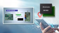
STMicroelectronics' G3-PLC certified SoC and chipset. Image used courtesy of STMicroelectronics
Following this announcement, a few questions come to mind. What is the G3-PLC Alliance, and what value does it bring to the industry? What methods are used by the Alliance to facilitate this benefit?
This article aims to briefly examine the G3-PLC Alliance before digging a little deeper into the physical layer requirements that the STMicroelectronics' hardware was recently certified.
The Rundown on the G3-PLC Alliance
The G3-PLC Alliance is a consortium of over ninety members and was created to support the standardization of smart grid technologies, principally through the use of power line communications, and most recently, radio links.

The newly standardized G3-PLC-Hybrid network. Image used courtesy of G3-PLC Alliance
In addition to growing its membership, the Alliance's mandate is to develop the frameworks for interoperability among vendor technologies and ensure that all vendor technologies within the consortium meet strict requirements with compliance testing. However, what is the process for getting certified?
Getting Certified With G3-PLC Standards
There are three main steps to G3-PLC certification. First, the certification process for the G3-PLC Alliance is closed doors, meaning that only members can access the details on the program, procedures, and test plans.
This requirement to join the Alliance to access the certification details is a double-edged sword.
It means that the Alliance must drive significant value for its members to entice them to join. Considering that the Alliance includes major industry partners, like STMicroelectronics, Honeywell, and ROHM, clearly indicates that there is indeed a demand for standardization in this area of industry.
Beyond the requirement to join, two other criteria have to be met before being allowed to test for certification:
- Participate in a “PlugFest," an interoperability seminar with other G3-PLC Alliance members, usually held annually.
- Be the owner of the device, which has been designed to be compliant with G3-PLC standards.
Additionally, any equipment (example: a smart meter) seeking certification must contain a pre-certified G3-PLC chipset within to begin the testing process.
So, what does a compliant chipset look like? The answer might become apparent by examining the protocol stack and the hardware interfaces that can support this protocol.
The G3-PLC Protocol Stack Data Link and Physical Layers
The STMicroelectronics' ST8500 system-on-chip (SoC) PLC solution has continued to achieve standards' benchmarks over several years, including adding wireless support late in 2019.
Its recent certification against the March 2021 G3-PLC Hybrid standards indicates performance compliance with the G3-PLC protocol stack.

G3-PLC Alliance's power line communication stack. Image used courtesy of G3-PLC Alliance
Built upon IEEE (802.15.4) and IETF (6LoWPan) specifications, the G3-PLC protocol stack is exclusively concerned with the physical and data link layers using a hardware abstraction layer to obfuscate the application layers from the physical communication links. This obscuring allows the software to ignore the medium of delivery and only focus on media requests.
The most interesting aspect of this improved protocol is the LOADng routing protocol, which selects the medium based on the following formula:
\[LinkCost_{RF} = max(C_{i \rightarrow j}, C_{j \rightarrow i}) + AdpKrt_{RF} \star \frac{NumberOfActiveRoutes_{RF}}{MaximumNumberOfActiveRoutes} + adpKh_{RF}\]
The existing routing protocol formula has been expanded to consider the presence of an RF link and accordingly decide whether the link cost between two nodes is more efficient via PLC or RF.
Once the medium has been resolved, the hybrid abstraction layer will set the appropriate flags for transmission through the physical layer.
Now that the protocols are understood, what hardware does STMicroelectronics use to enable PHY interfaces?
A Look at STMicroelectronics’ ST8500 & S2-LP Hardware Interfaces
The ST8500 SoC is paired with the S2-LP, which is an ultra-low-power sub-GHz transceiver. The S2-LP chipset, seen below, operates in the ISM bands, including 433, 512, 868, and 920 MHz.

The S2-LP block diagram. Image used courtesy of STMicroelectronics
The S2-LP can interface with the ST8500 via an SPI FIFO (first in/first out) channel or a reprogrammable GPIO.
Rounding out the hardware trifecta for this certified solution is the STLD1, a line driver which ensures linear power amplification for signals transmitted on the power lines.
Sure to be the first of many vendor options certified with the new G3-PLC Hybrid standards, STMicroelectronics has demonstrated a focus on future-proofing PLC technology through robustness and flexibility.
Interested in past power line communication advancements and technology? Read more in the articles down below.
Power Line Communication (PLC) Modem Chips Streamline Smart Meter Design
Maxim’s 2-Pin PLC Chip Saves Circuit Space and Power for True Wireless Earbuds
Where KNX Stands in Building Automation Designs