Facebook
 Google
 GitHub
 Linkedin
New Switching DC/DC Regulator from TI Shows Improvements in Regulator Implementation
Switch-mode power supplies, such as the TPS565201 from Texas Instruments, are becoming easier to implement.
Switch-mode power supplies, such as the TPS565201 from Texas Instruments, are becoming easier to implement.
DC-to-DC switching regulators include the step-down (buck) regulator, the step-up (boost) regulator, and the step-up/step-down regulator, which is also known as (can you guess?) the buck/boost regulator. For this article, we'll focus on the step-down (buck) regulator. In particular, we'll take a look at the TPS565201 switching regulator from TI.
Input Voltage Range and Output Voltage Range
Datasheets for step-down DC-to-DC switching regulators, such as the TPS565201, will have specifications for Input Voltage Range and Output Voltage Range. TI's TPS565201 lists the following specs:
- Input Voltage Range: 4.5V to 17V
- Output Voltage Range: 0.76V to 7V
The following point shouldn't be a surprise to you, but if it is, just consider this a learning moment: just because there's an output voltage range to pick from doesn't really mean that you're free to pick any value within this range... you have to consider the input voltage (VIN). More specifically, the output voltage must be less than the input voltage; that's why it's called a step-down regulator.
For example, if your desired VOUT is 6.0V then your input voltage can't be anything less than 6.0V. In fact, in most step-down regulators, VOUT can't even be the same as VIN. The output voltage must be greater than the input voltage by some defined amount. In the land of linear regulators, this voltage difference is normally referred to as the dropout voltage, or VD. However, the various manufacturers of switching DC/DC regulators address this voltage difference in diverse ways.
TI reveals the information, at least for this part, in a section called "Power Supply Recommendations". For the TPS565201 device, the Power Supply Recommendation section (section 9) states: "...the minimum recommended input voltage is VO / 0.83." So revisiting the VOUT = 6.0V example, VIN must be ≥ 7.22VDC.
External Compensation Components (Or Lack Thereof)
Let's get back to the ease of implementation. The reason this regulator is easy to implement is that it requires no external compensation components. This is a big deal.
During my time as a test engineer for solid-state drives, we were faced with a sporadic (yes, random, and awfully random...sometimes the occurrence was every few minutes while other times it was many hours) power supply "glitch." When multiple phone conversations to the vendor failed to yield results, we ended up "inviting" a whole team from the vendor to assist us with our troubleshooting efforts. The root cause was the wrong selection of external compensation components. So, because the TPS565201 requires no external components, this is a big two thumbs up from me!
Efficiency Curves
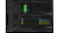
Sometimes efficiency curves can be a bit deceiving if you don't look closely enough at the details. For example, Figure 13 of the datasheet is Efficiency vs. Output Current (see the figure below).

Figure 1. Efficiency vs. Output Current. Figure taken from the datasheet (Figure 13).
These efficiency curves look really good, but take note of the VOUT (5V) and VIN (9V, 12V, and 15V) specs. Other VOUT and VIN combinations may be worse, or better! This observation of mine isn't a dig at TI, in fact these efficiency curves are normal. After all, it's not possible to list all VOUT vs. VIN combinations on this one datasheet.
The good news is that TI, and most other manufacturers, would be happy to provide you with efficiency curves based on your own custom design. Just give them a call or drop them an e-mail. In my experience, TI has been very accommodating with assisting engineers with their designs.
Thermal Shutdown
Regarding thermal shutdown, section 7.3.6 of the datasheet states, "The device monitors the temperature of itself. If the temperature exceeds the threshold value (typically 172°C), the device is shut off."
Side Note: What does footnote (1) ("Not production tested") next to the thermal shutdown spec, in section 6.5, really mean (see figure below)? I read this as, "Yes, this is a brand new part and, yes, TI is eager to get it into the hands of users—but they are still testing the product so don't assume that the thermal shutdown spec is rock solid because they have the right to change it at any time." Okay, fair enough...I'm not mad at them. In fact, I'm happy they disclosed this bit of information; their transparency is great.

Figure 2. Thermal shutdown information. Table taken from the datasheet.
Now, back to the thermal shutdown definition. Hmmm, "the device monitors the temperature of itself". When I read this statement I was a little confused—what exactly is meant by "itself?" Is "itself" the package temperature, or is it the junction temperature, or something else? Actually, it can't be the package temperature, because I've never seen or heard of a voltage regulator operating in such a high-temperature environment. And, it can't be the junction temperature because that spec is already listed (-40°C to 125°C).
After asking my good friend Mr. Google, I found documentation (page 11) from TI discussing the subject. It turns out that the temperature in question is the die temperature. And what's more, this advertised temperature (although not "production tested", smiley face) is higher than the "usual" temp of 160°C, as called out in the TI document mentioned above. It would be nice (read, convenient) if TI would specify “die temperature” regarding this spec.
Have you had a chance to use this part from TI? If so, please give me some firsthand-experience feedback.