 Facebook
 Google
 GitHub
 Linkedin
Teardown Tuesday: HB100 Doppler Radar Module
Join us as we crack open an HB100 Doppler radar module and delve into the mysteries of RF component design.
In this special edition of Teardown Tuesday, we crack open an HB100 Doppler radar module and delve into the mysteries of RF component design.

Image courtesy of Gikfun via eBay.
The HB100 Doppler Radar module costs about $5 from the usual online suspects, which is down at the “insanely cheap” end of the spectrum when you’re talking about 10Ghz radio gear.
Does it work? Surprisingly, yes. It needs some support components for most uses (like a post-amplifier for the “couple of millivolts” signal it outputs) but does its part of the job well enough.

Theory of Operation
The basic idea of Doppler radar is that we’re not doing “distance” pulse ranging. That requires precise speed-of-light calculations and expensive components, in order to emit pulses of radio energy and count how many nanoseconds they take to echo back.
Instead, these modules constantly emit a low-level radio beam and then mix the return signal with the original to generate heterodyne “beat notes” which occur if one frequency has been shifted slightly.

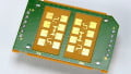
The copper squares around the edge are patch antennas. The left pair is the TX and the right pair the RX.
More technically, a good linear RF mixer will generate two sidelobes at the sum and difference of the two frequencies. So if we’re emitting a 10Ghz wave and getting back a 10.0001Ghz wave, the result of mixing those will be 20.0001Ghz and 100Hz signals. (100Hz is a low G2 on the piano.)
What would cause our return signal to be a different frequency from the one we emitted? Doppler shift! Anything moving towards or away from our antenna will introduce a shift (and therefore beat note) proportional to object speed and your carrier frequency.
When using the HB100 for “movement sensor” applications, the output just goes to an appropriate frequency filter for the range of movement you’re looking for (like a person walking) and that can flip a light switch or open an automatic door
Now, most mixers are imperfect, which means we’ll still have a good amount of the original 10Ghz signals in there too… but since we’re really only interested in the low-end frequencies coming out of the mixer, we can just scythe off everything above a few hundred kilohertz (by using NON-microwave-rated components like common audio amplifiers) and all we’re left with is the ‘doppler’ signal we wanted.
Since low-frequency signals are much easier to preserve and amplify than RF and the frequency difference so great, in practice that means we can hear very faint Doppler signals next to our relatively powerful carrier signal. Even with a really sloppy filter.
It’s also the case that the exact emitted frequency can drift quite a bit and yet the mixer results barely change, making the modules immune to most temperature and power supply variations.
However, the HB100 isn’t immune to 5v on the IF pin, I discovered. That will kill it dead and trip your DC supply protection to boot. Which is the perfect time to tear something apart!
Teardown
So, what’s inside? Everything is under a metal shield, which comes off easily enough.

What sorcery is this?
Frankly, I was rather shocked by what I found. I wasn’t expecting much, but I got far less.
I don’t know who designed this, but they were a master of the black art of Radio Frequency waveguide engineering. I am impressed. The PCB, itself, is a major component. Not only for the patch antennas but also several RF filters, the local oscillator, and the mixer are all largely made from peculiarly-shaped PCB tracks.
Apart from the PCB, there are only five “components" on the board.
Five passive components to implement a Doppler radar module. C’mon. You have to be impressed by that!

Local oscillator section. +5V power comes in from the top right through the resistor.
Note the weird “quarter circles” which form part of the tuned oscillator. Those are RF filter capacitors.
At first, I couldn’t figure out how the local oscillator worked. A major component was clearly the white disk that I thought was a potted inductor, because the adjustment screw in the case changed its distance slightly to this disk, (and then set with thread-lock but otherwise wasn’t physically touching) so I assumed (wrongly) it was altering the magnetic flux of a coil.

But on closer inspection, the white disk didn’t have any leads and wasn’t electrically connected to anything. I even broke it open slightly to check it didn’t have wiring inside, but it was solid ceramic.

This is actually a Dielectric Resonance Oscillator. The ceramic disk (usually made from Barium Titanate; Ba2Ti9O20) acts as a resonant chamber for RF energy. Like a tiny organ pipe, the tone is set by the shape and size of the material.
These resonators are slightly odd in that the electric field extends beyond the surface of the ceramic, unlike a “metal box” resonance chamber where the field stops at the walls. Therefore, you can interact with the field by placing conductive elements nearby, like the adjustment screw.
Next to the ceramic resonator on the PCB are two ‘fingers’ which act as the driver and sense elements that connect to the RF power transistor. So any initial resonance (or just noise) in the ‘tank’ is amplified via feedback until the oscillator is in full resonance, generating a strong 10Ghz signal.
Genius!

That seems like a normal DC decoupling capacitor between the local oscillator and the output antenna but I honestly wouldn’t be surprised if it was another bizarre ceramic RF element of some kind.
After that, most of the signal goes out the other side of the board to the antenna patch, but some is redirected down the “F” element into the mixer.

PCB trace "F filter" taps a small fraction of the transmit signal to feed the mixer. The receive antenna comes in from the via at the bottom left.
Don’t be confused by the fat copper traces—10Ghz is weird and likely very little of the transmitter power makes it through this filter. You want only a fraction to stay behind for mixing.
And then finally the mixer, itself, which contains the greatest amount of black magic on the board.
It's one transistor. Which also performs as the receiver amplifier for the antenna feed from the bottom left.
Electrically (at DC), the receive antenna is directly connected to the IF output through a couple of copper traces—which can’t possibly work. It’s also connected across two terminals of the same transistor on the way and the third terminal is grounded, which can’t possibly work either.
At 10Ghz, things are going to be a very different story. One pin of the transistor is being lightly powered by the local oscillator and the other two pins are seeing phase-shifted versions of the receive signal from the antenna. Somewhere in the middle, the RX signal is getting amplified and also modulated by the TX, which is equivalent to a poor and trashy mixer.

The antenna feeds connects to two pins of the same transistor? At 10Ghz, this "U" is a center-tapped inductor.
The output of the mixer is tapped by a thin trace that will reject most of the higher frequencies we no longer care about. Another quarter-circle PCB RF capacitor that bypasses much of the res, and the remainder of the (dirty, dirty) signal comes out the IF pin at the bottom right of the board.

The IF signal trace goes out the bottom right.
To put it simply, this module is a masterpiece of design elegance. There’s nothing you can take away without fatally compromising the circuit. Even moving the PCB traces around or using a different kind of board material would mess it up. This is obviously designed for mass-production by the millions after generations of refinement.
It’s also pretty obvious now why accidentally putting 5V on the IF pin would kill the module. It would all flow straight through that mixer transistor to ground. More than a few hundred milliamps and that small-signal RF semiconductor will melt.
Schematic
Putting it all together, the circuit diagram for the HB100 looks (roughly) like this:
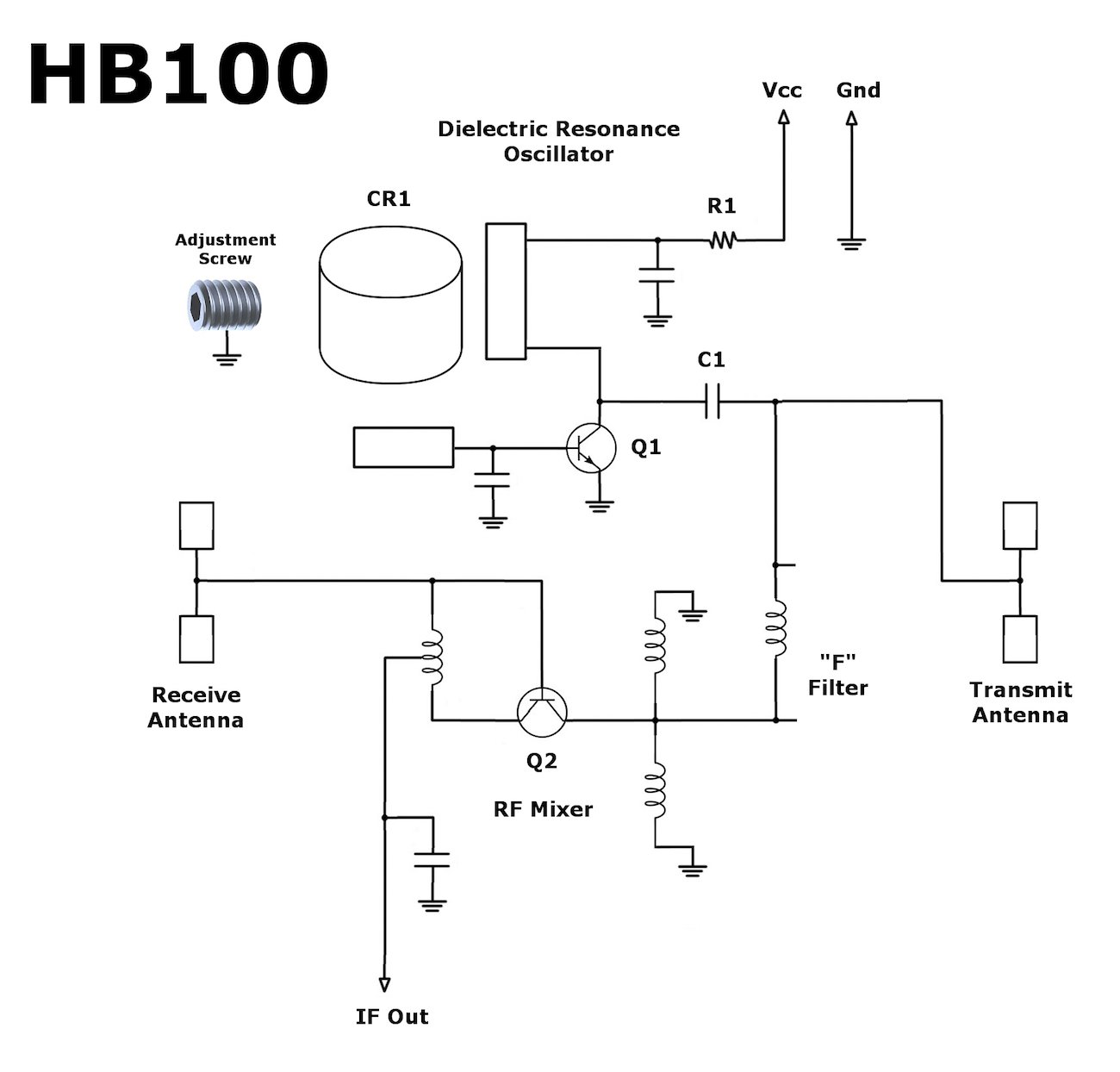
I'm not entirely sure of the orientation of Q2. I wasn't able to find data on the transistors, so I'm just guessing they're bipolars.
Hacking the Module
There’s not much to work with here. You can slightly adjust the frequency using the grub screw, but you’ll need an RF spectrum analyzer to figure out what frequency it’s on, Kenneth. The dimensions of the ceramic resonator set the “core” frequency so you won’t be able to change it much without physically altering it.
You can “pulse” the module and probably even modulate the output power if you wanted to use it as a low-rate 10Ghz transmitter. But there’s no receiver section to speak of, so all you could really do is interfere with automatic doors.
The ceramic resonator, itself, is quite interesting. Pure barium titanate has all kinds of useful properties. It’s piezoelectric, pyroelectric, ferroelectric, has a positive temperature coefficient, and a huge dielectric constant. It's not too hard to pop off the board, either, if you wanted it for experiments.
If you were hoping to get access to the I and Q ‘quadrature’ signals independently to figure out if the doppler signal was up or down shifted (indicating coming towards or moving away), then you’re out of luck. I don’t think the mixer works that way.
It does one thing and not incredibly well—but it is full of fascinating design choices!
Next Teardown: Vehicle Backup Sensor


wow, just wow!!! I am impressed!
Amazing!
Your a couple of orders of magnitude off on your mixing calcs , otherwise great :0)