 Facebook
 Google
 GitHub
 Linkedin
Teardown Tuesday: Wireless Lamp
In this teardown Tuesday we will take apart an Ikea smart lamp that can be controlled via an external remote.
In this Teardown Tuesday, we will take apart an Ikea smart lamp that can be controlled via an external remote.
Home automation is all the rage these days. Our thermostats, toasters, and refrigerators are all becoming wireless and interconnected.
In this Teardown Tuesday, we'll crack open a wireless lamp and see what makes it so tech-forward.
The Lamp
The lamp is of the LED variety using an Edison screw fitting (the live connector is found at the tip of the bulb while the neutral connector is the screw fitting, itself). One advantage of the Edison screw fitting is that the screw fitting on the lamp holder is connected to neutral which means that (in theory) if the system was live and someone was to put their hand into the bulb holder they will not be electrocuted unless they push their finger right to the base where the live contact is found.
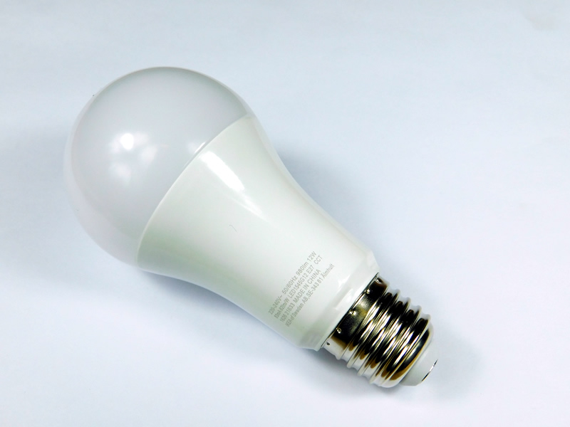
The Ikea lamp
Getting access to the guts of the lamp was very difficult considering that the lamp is designed to not be taken apart (i.e., no screws and molded fittings). The first attempt was to cut the plastic dome that sits above the LED circuit board. This proved pointless as the screws found on the LED board where just to keep it in place against the main controller board. The second attempt was to go from the bottom by cutting into the screw, itself. After cutting the small depressed tabs, the screw came off, exposing the wire connectors and the unit that contains the electronics slide out of the main casing.

The lamp cut open

Wire connectors that make contact with the screw and live contact

Main circuit holder and LED circuit board

Pin connectors used to make contact with the LED board
This teardown was nearly abandoned when the main circuit board was removed from the casing due to a rubbery / silicone based filling. Luckily, the material was easily removed using a small screwdriver and some patience.
The filling may have been needed as protection against mains voltages as well as the need to prevent the circuit from moving around inside the lamp. The exact material of the filling is unknown but is most likely to be a silicon that can easily be torn.

Silicon filling used to keep the circuit from moving
After 20 minutes of pain and cut fingers, the silicon material was removed, exposing the internal circuitry of the lamp. Interestingly, the silicon material shows the imprints of the components and one of the component idents can even be seen in the filling material.

The exposed circuit

The imprints of the components including component ident (middle right)
The main hardware includes a circuit that consists mainly of power-related components on the top, a wireless module (most likely 2.4GHz), and many surface mount parts on both the top and underside of the PCB.
There are a few giveaways that the module, which sits on the PCB, is a wireless system. The first piece of evidence is the PCB antenna that sticks out from the PCB. The second piece of evidence is the use of a metal shield which is common in environments where EMC (electromagnetic compatibility) is very important. The metal enclosure is not needed to ensure that the module works correctly. Rather, it is there to make sure that electromagnetic waves generated by the module (any switching signal generates an emission) are captured and do not interfere with other circuits. Thirdly, wireless modules commonly have “cut vias” as contacts on the edge which commonly provide GPIO and peripherals such as I2C and UART.

The main circuit

The wireless module can be seen here (white)

Close-up of the wireless module

Wireless module text
The underside of the circuit shows surface mount components and how the wireless module is attached to the main PCB. The module is inserted into a routed area that allows for the contacts to be soldered to PCB pads.
Such a technique has some advantages and some disadvantages over mounting the module flat against the PCB. Such mounting techniques prevent the module from taking up valuable room which is incredibly important in this application (the whole control circuit has to fit inside a lamp). However, structural integrity is compromised as any axial forces on the module will easily break traces and pads on the PCB. This may be one of the reasons the circuit was encased in a silicon filling.

Underside of the circuit

Close-up of the BAV5RB IC (unidentifiable part)
The wireless module has no external part numbers which, in a teardown like this, is totally unacceptable. The module, itself, is not the wireless integrated circuit itself. The module instead consists of a circuit board with several parts included. The metal case was very easy to pop off, which revealed all the components involved.
Fun fact: Wireless modules, while more expensive than the stand-alone ICs that make them up, are commonly certified with either CE or FCC. This makes it very easy to implement such a module in a pre-existing circuit because emissions from the module will be at acceptable levels and thus do not require extensive testing which is very expensive.
The IC at the core of the module is the EFR32MG, which is one of the Mighty Gecko ICs produced by Silicon Labs. It is a wireless System-on-Chip that includes many features including 2.4GHz/434MHz wireless operation, ARM Cortex M4 core, timers, UART, I2C, ADC, DAC, counters, and much more.

The wireless module in all its glory
The Controller
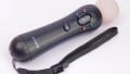
The controller for the light bulb is very simple yet elegant in design, consisting of brightness controls, color change, and (most importantly) the on/off switch. The switch, itself, can be mounted pretty much anywhere using the sticky pad that comes with the product. Of course, this is an electronics teardown so we can safely ignore the many potential applications of sticky pads and get right into ripping the plastic apart to get to the internal circuitry.

The controller
One problem with the controller is that it is very difficult to get into as it is a molded part (i.e., no screws or fittings). With a little bit of brute force, the PCB was removed, which revealed the real simplicity of the design. The buttons are small metal tactile switches which the plastic pieces push against.
The top side of the PCB also shows plenty of stitching via which suggests the presence of EM-emitting parts. For those who may not know, stitching via (the hundreds of small via that are found on power planes) are used to create a crude faraday cage around traces which help to prevent stray EM emissions from interfering with other nearby electronics.

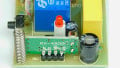
The top side of the controller PCB
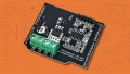
The underside of the controller shows a wireless module, battery holder, and few surface mount parts that most likely perform decoupling, regulation, ESD protection, and various other analog suppressing techniques. One interesting feature of the PCB is the lack of any planes near the PCB antenna of the module. The planes help to absorb EM emissions which would be bad for a wireless module hence the lack of planes!

Underside of the controller PCB

Close-up of the battery holder
Removing the metal shield on the wireless module confirms that the module is identical to the module found in the lamp (EFR32MG). It would be unusual to use two different modules for transmission and reception (especially considering how cheap electronics are becoming).

Inside the wireless module
Summary
The IoT may not necessarily apply to this product but what it does show is an increasing use of wireless systems to control devices. Home automation is still in its infancy (I still open my curtains by hand, make my own lunch, and fiddle with the thermostat frequently) but it won’t be long before it all kicks off.
Currently, there are several protocols that are trying to become the main standard (just like the war between VHS and Betamax) but which one will win in the home automation race remains a mystery.
Next Teardown: Bluetooth Laser Distance Measurer


Good work…
I would *love* to find software-security-related info in this tear downs. IoT devices will no doubt invade us (pun intended), and being conscious not only of the hardware stuff but the software stuff in them should now be considered a must.