 Facebook
 Google
 GitHub
 Linkedin
Teardown Tuesday: Bluetooth Laser Distance Measurer
What's inside the Suaoki Bluetooth laser distance measurement tool?
This 20-meter laser distance measurement tool sports a touchscreen and Bluetooth connectivity. In this teardown, we'll look at the circuitry inside.
About the Measurement Tool
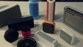
The Suaoki D5T laser measurement tool provides direct distance measurement that, when coupled with the built-in inclinometer, can be used to automatically calculate the horizontal and vertical distances to a target object within 1/12 of an inch. It has several other features such as area calculation, multiple measurement units, and the ability to change the reference point to the front, center, or rear of the device.

Suaoki Bluetooth laser distance measurement tool. Image courtesy of Amazon.
The device also features Bluetooth connectivity and pairs with an iPhone and Android app, "Sketch iMeter." However, during testing, the app repeatedly crashed and was unable to save any of the data points shown on the bottom of the app screen. The manual states (page 15): "As this product do (sic) not have the function of data recording, the Import Record function in the app can not be used."
Since the app is capable of initiating data recording and displaying data from the device, it appears that the Bluetooth communication works, but the app is unable to parse the data, which is a problem that should be able to be fixed in future software releases.
The device is currently available for about $45.
Disassembling the Device
The device can be disassembled by removing the four self-tapping thermoplastic screws on the backside of the case.
Mild prying can remove the circuit board from inside the top half of the case. There is a flexible printed circuit connector that connects the touchscreen to the main circuit board. Disconnect that before removing the main circuit board.
The touchscreen is secured in a bezel in the top half of the case from the outside. Removal is accomplished with gentle pressure from the inside after detaching the flexible printed circuit. Once disassembled, the circuit board, screen, and touchscreen can be reattached.
See the video below for more information:
What's inside?
Inside the device is one main circuit board with a two smaller auxiliary boards attached. All components are surface mount soldered throughout the device. The two auxiliary circuit boards are for Bluetooth data transmission and for the laser detection circuit.

Top and bottom of the main circuit board
| Top Side Marking | Description | Cost | Datasheet |
|---|---|---|---|
| none | Laser Diode -- Red | unknown | Datasheet |
| none | Laser Diode -- Infrared | unknown | Datasheet |
| STM32F 030C8T6 GH208 98 CHN 602 | ARM based 32-bic MCU | $2 | Datasheet |
| CC2541 F256 TI 59J PE67 | Bluetooth and System-on-Chip | $3 | Datasheet |
| 5351 B844 541 | I2C CMOS Clock Generator + VCXO | $1 | Datasheet |
| 251WD | Hall Effect Switch -- Unknown Manufacturer | $0.20 | Datasheet Datasheet |
| 263 8452 DOP | 3-Axis accelerometer | $1 | Datasheet |
| Avalance Photodiode | Datasheet |

(1 and 2) Laser Diode (Red)
Two laser diodes are present in this circuit. (1) A visible red laser diode with a collimating lens is projected from the end of the device to a distant object. While it is is on, the second, infrared laser diode (2) turns on and off. The first laser is used to aim the device, and the second laser is used to determine the distance to target, likely through light pulse phase shift or time-of-flight measurements. To learn more about laser rangefinding techniques, see this paper from UT Dallas (PDF).
(3) STM32 (Orange)
The STM32 microcontroller is based on the ARM Corex-M0 microprocessor. This microprocessor shows up in teardown after teardown (see Miposaur and Pulse Oximeter). The lower number of instructions corresponds with fewer gates and decreased power consumption. This microcontroller is responsible for controlling the other integrated circuits on the board, interpreting the touchscreen, output to the display, and the Bluetooth communication subcircuit.
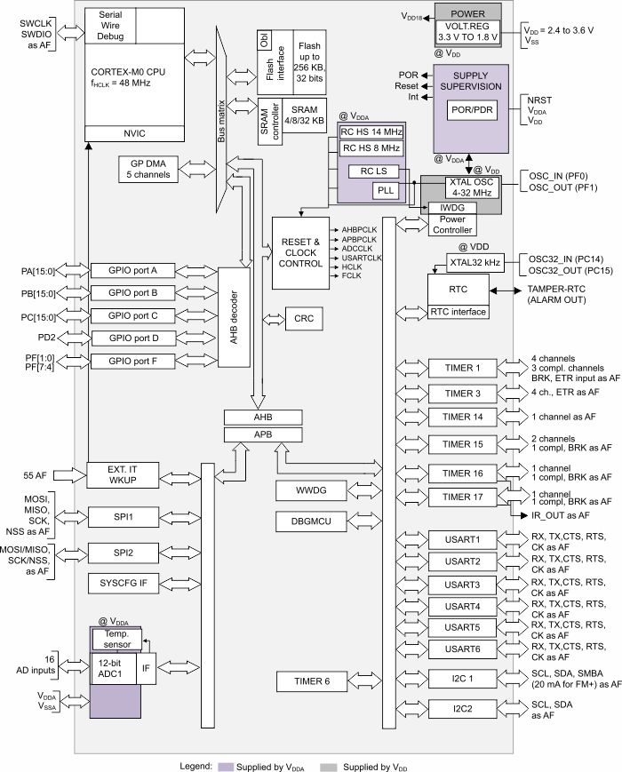
Image courtesy of STMicroelectronics (PDF). Click to enlarge
(4) Bluetooth Daughterboard (Yellow)
This module is attached to the main circuit board with castellated solder holes. It is based on the Texas Instruments CC2541 2.4 GHz transceiver. Complete modules can be purchased for a few dollars on eBay or AliExpress for slightly more than the cost of individual chips available at Digi-Key.
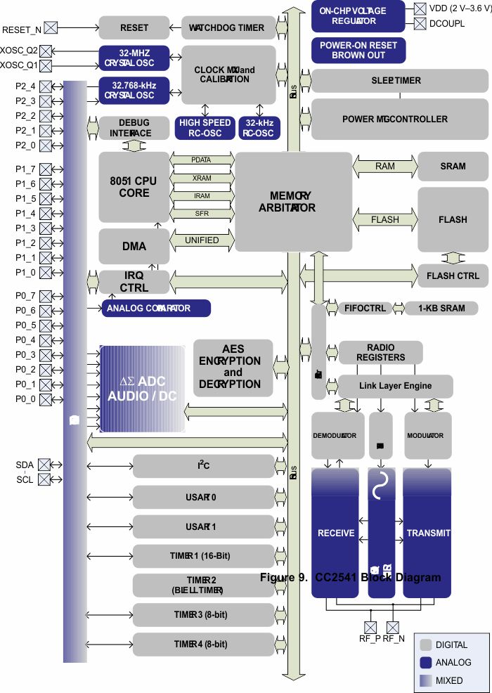
Image courtesy of Texas Instruments (PDF). Click to enlarge
(5) Si 5351 (Green)
Silicon Labs 5351 I2C controlled clock generator and voltage-controlled crystal oscillator is capable of providing three independent frequencies up to 20 MHz in either free-running or synchronous clock signals. Various configurations of the chip (A/B/C) and footprints (10 pin-MSOP and 20-pin QFN) provide up to 8 output signals. The datasheet also claims: <70 picosecond output jitter, exact frequency synthesis at each output (0 ppm error). Due to the location on the circuit board, I believe this circuit is used to modulate the output of the laser diodes.

Image courtesy of Silicon Labs (PDF).
(6) Hall Effect Switch (Blue)
This rice-grain sized IC acts as the main power switch for the device. The top-side marking offers no indication of the manufacturer and the number/letter code is likely a date/batch code, so unfortunately there is no way for me to easily determine which type of switch is present in the device.

There are several benefits to using a Hall effect switch or sensor in a circuit including:
- Hall switches can be installed by pick-and-place machine along with other SMD components, reducing time and manufacturing cost. (Mechanical switches are expensive and might require hand soldering.)
- Hall switches are resistant to mechanical and chemical fouling. (They can be used in harsh environments.)
- Hall switches do not bounce.
Hall effect switches have their disadvantages as well:
- Hall switches require connection to power to function (although current consumption in the off state is very small).
- Hall switches can source and sink less current than mechanical switches
- The Hall effect requires temperature compensation.
- There is no mechanical feedback to indicate an on or off condition. This can be disconcerting for some users, and deadly for others. An amazon reviewer of this device listed the slider as a possible reason to return it as "the device feels a bit cheap". This problem can be solved by our mechanical engineering counterparts at virtually no cost by creating two indentations in the case and a cantilevered cam in the slide to provide a tactile "click" in the on and off position.

(7) Light Detection Circuit
While playing with this board, I put a probe on the solder pads near the pink box at position 7 and detected ~100 VDC. Avalanche photodiodes require such voltages, and this is the location on the circuit board where the lens at the front of the device focuses light on a clear 3-pin photodiode.
It seems that a pulse of light is emitted by the laser through the same lens that it is later detected. The microcontroller appears to determine the time between pulses and uses that, along with the speed of light, to determine the distance to objects.
(8) Power (Pink)
Voltage from the batteries is boosted and regulated in this section of the board to provide the rest of the devices on the board according to their requirements.
The main circuit board also holds a 3-axis I2C output 12-bit accelerometer that is used to provide the angle of inclination of the device.
Conclusion
Laser rangefinders, which were once only available to the military and businesses, have become increasingly available to home handyman and amateur robot builders. Multiple manufacturers have laser distance measurers (Bosch, Milwaukee, Stanley, Fluke) in the affordable price range and many component suppliers have options available for incorporation into your projects.
If I could give a note to manufacturers with Bluetooth measurement devices, it would be this: Consider emulating a Bluetooth keyboard and sending the data from your device as a comma separated or tab separated sentence, followed by a CR/LF. Consumers can then connect it to their laptops, their phones, or their tablets when they wish and send the data directly to their preferred app without the restrictions imposed by an incomplete and nonfunctioning app.
Featured image used courtesy of Amazon.
Next Teardown: Occipital 3D Structure Sensor


In range finders of this type, time of flight isn’t used. Instead, laser emits light using short pulses (with light beam length inside each pulse in 3-30 meters range, corresponding to frequency of 10-100MHz), and avalanche photodiode determines how much light got into it right after laser finished emitting pulse. If target is close, most of the beam was already reflected and absorbed when emitting phase ended, so photodiode won’t see much beam left. The longer is distance to the target, the longer part of the beam will come during laser off-state, thus producing higher response signal. Pulse width can be dynamically adjusted in order to find maximum response (thus finding target distance), or it can go through a set of predefined values, with some algorithm processing received photodiode outputs for each pulse width.