 Facebook
 Google
 GitHub
 Linkedin
Teardown Tuesday: Occipital 3D Structure Sensor
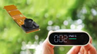
Occipital's structure sensor works with iPads and other devices to create 3D models of the environment. This article takes a look inside one.
Occipital's 3D structure sensor scans environments with an iPad to create 3-dimensional models. In this teardown, we disassemble one to determine what is inside.
About the Structure Sensor
Occipital's 3D Structure Sensor began as a $100,000 Kickstarter that collected over 10 times that amount. The device is designed to attach to iPads or other devices and collect 3-dimensional depth information about the environment. All About Circuits received a sensor from Occipital in late December for the purpose of a Teardown.
There are several iPad apps for the structure sensor, as well as a Standard Developers Kit (SDK), and forums with information for your hacking pleasure.
The video below is by Occipital and shows how the structure sensor works.
Dissassembly
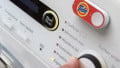
The structure sensor is built around an anodized aluminum body. Disassembly begins by removing four screws on the bottom of the sensor with a T5 screwdriver.
To remove the primary circuit board, you must first detach two flexible printed circuit cable connectors (FPC) and desolder one red and one black wire on either side of the FPC in the middle of the board. This allows the main circuit board to be removed. Remove two more screws that hold the power and data connector circuit boards in place and then look at the opposite end to see another screw buried deep inside the case. All visible screws should be removed before attempting to remove the lens side of the case.
Once the three screws inside the case are removed, the lens falls away and provides access to the front of the device. Two screws hold the IR emitter in place, and four screws hold the IR camera. Removal of the USB and power connectors is easy once the IR camera is out of the way.
Do not attempt to remove the lens cover to the plastic carrier. The glue is quite strong and the glass is quite fragile. If you crack it, you should order a replacement of both pieces.
See the video below to learn how to take your structure sensor apart.
A Look Inside

Front view and reverse view of the main circuit board.

Front view and reverse view of the USB and power interface boards. These boards fold around a flexible middle cable.
| Top Side Marking | Description | Cost | More Information |
|---|---|---|---|
| DRV592 Ti47T C09L | PWM Controlled H-Bridge Thermoelectric Cooler Driver | $5 | Datasheet |
| Rectangular Connector | |||
| BQ 24160 TI 441 A4NX | Li-Ion Battery Charger | $2 | Webpage |
| FPC Connector | |||
| HA08 TI 55k D320 | Quadruple 2-input positive-AND gates. | <$1 | Webpage |
| 6C 3521 N0717 | Buck-Boost DC/DC converter (1.2V, 1.8V, 3.3V output) | $5 | Webpage Datasheet |
| M29W160EB "ST" 70Za6 L 99A5W VS MYS 99 527 | 16MB Flash Memory | $1 | Datasheet |
| Prime Sense PS1080 1314 TW D5S850-2 1080A6SSAGR | 3D Depth Sensing System-on-Chip | $3 | Overview |
| TI56A9271 OPA2376 | Low-Noise, Low Quiescent Current, Precision Operational Amplifier | ~$1 | Datasheet |
| AT 1449D XMEGA64A4U CU-K A2NHYA | 8-bit AVR microcontroller with 64 kB onboard flash | $4 | Webpage Datasheet |
| 133 3959 1521 | Unknown | Unknown | Unknown |
The sensor is built around a single main circuit board with several offboard connectors to connect the IR camera, IR structured light emitter, power, and USB.

Front and reverse of the USB and power (left) and the main circuit board (right).
The large aluminum case acts as a large heat sink for a thermoelectric cooler (TEC) that is hidden underneath the IR camera. The rectangular hole in the circuit board accommodates the protrusion in the case that holds the thermoelectric cooler.
(1) DRV592 H-Bridge (Red)
The DRV592 is a Pulse Width Modulation (PWM) driven high-current H-Bridge that controls the thermoelectric cooler. It is capable of outputting ±3 amps. You'll notice that the 32-pin VFP package has far more pins that most H-bridge microchips. That is because there are five terminals tied to the semiconductor die for each output to the TEC, six terminals tied to Ground, and eight terminals for Vdd input.

Schematic for the DRV592 H-bridge. Image courtesy of Texas Instruments.
(2) Rectangular Connector (Yellow)
This pair of rectangular connectors connects the main circuit board to the data and power connectors.
(3) BQ24160 Battery Charger (Green)
The high current demands of the TEC require an onboard power source by way of a lithium ion battery. This BQ24160 is a dual-input 2.5A switchmode Li-ion battery charger circuit with I²C control and integrated temperature monitoring by means of a thermistor in the battery pack.

Schematic for the BQ24160 battery charger. Image courtesy of Texas Instruments
(4) SN74AHC08 AND Gate (Blue)
This appears to be a new version of an old logic circuit, an SN74AHC08 quadruple 2-input AND gate.
I'm not entirely certain what the designers are using it for, but it's good to remember that not every problem needs to be solved by adding another microcontroller. The 7400 series of logic circuits can solve a wide variety of problems quickly, reliably, and inexpensively.
(5) Flexible Printed Circuit Connector (Lilac)
Two flexible printed circuit connectors are on the main circuit board for connection to the IR camera and IR structured light emitter.
(6) LTC3521 Buck-Boost Converter (Turquoise)
The LTC3521 is a triple output Buck/Boost DC power supply microchip with one buck/boost 1A output and two 600 mA buck outputs. Many of the passive components in close proximity to the IC are support components for this device.
.png)
Schematic of the LTC3521 converter. Image courtesy of Linear Technology
(7) M29W160EB Memory (Pink)
The M29W160EB is a 16MB Fine Pitch Ball Grid Array (FBGA) memory used as a buffer for the 3D sensor.
(8) PrimeSense PS1080 Microcontroller (Orange)
The PrimeSense SoC Carmine 3D sensor is the primary microcontroller that generates a three-dimensional scene. It controls a structured light sensor that sends out a regular pattern of infrared dots and locates them with a CMOS sensor. The microcontroller creates a VGA size depth image and sends the data through the USB interface. This is in contrast to the design of the Leap Motion Controller, which appears to process data entirely outside of the device.

Block diagram of the PS1080 SoC. Image courtesy of PrimeSense
(9) ATxmega64A4U Microcontroller (Teal)
This is the ATxmega64A4U microcontroller that undoubtedly controls everything from the intensity of the IR LEDs to the H-bridge, to the Primesense 3D sensor. It has all the capabilities one might expect of a modern microcontroller, including multiple peripheral communication options. This particular configuration features 64k Flash, 4kB boot section, 2K EEPROM, 4k SRAM, and a 32 MHz crystal.
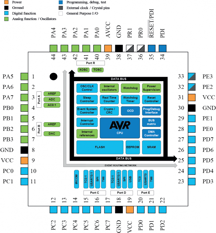
Block diagram of the ATxmega64A4U microcontroller. Image courtesy of Atmel. Click to enlarge
(10) Unknown (Brown)
I was not able to positively identify this component based on its top side markings alone. Based on its footprint and proximity to the microcontroller, my best guess is that it is a serial EEPROM. If a reader knows, or I find out in the future, I'll update the article.
Conclusion
Occipital's 3D structure sensor is a well designed device that incorporates a great deal of electrical and mechanical engineering. Applications include virtual reality, augmented reality, cinema, interior design, autonomous robots/motion planning, and more.
Next Teardown: Virtual Drumkit PCB for Drumsticks


Beautiful, but the programming is the real challenge. It is a conundrum like speech recognition, especially speaker identity. The raw data, even if perfect accuracy could be achieved, needs intelligence to be useful. And even a “dumb” program requires huge computational resources.
Hi,
I want to also measure the temperature at the same time. What is the spectral range of the IR camera?
Thanks,
Cem