 Facebook
 Google
 GitHub
 Linkedin
Teardown Tuesday: Robotic Floor Cleaner
Robotic floor cleaners have been available as consumer products for a number of years now but with a gradual drop in production cost and development of new technology, these cleaners are becoming cheaper. In this teardown we will look at a Robotic Floor Cleaner which uses "electrostatic forces" to remove dust and can clean a room with its "intelligent" obstacle navigation.
This little robot cleans floors with "electrostatic forces". It may not look like much, but it has a surprising sophisticated brain. Let's tear it open and see what makes it go!
Robotic floor cleaners have been available as consumer products for a number of years now. As production costs gradually drop and new technologies are developed, however, these cleaners are becoming cheaper.
One robot that is currently for sale supposedly polishes floors using an electrostatic method for dust removal. Surprisingly, the robot worked very well at cleaning my tiled floors but seems “unintelligible” in its motion. So here we will teard own a cheap $30 robotic floor cleaner and see what makes this thing tick.
The Outside
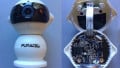
The outside of the robot shows a large material flange that holds onto the dusting material that uses “electrostatic forces” to attract dirt off the floor. Two buttons are on top of the device, both of which start the robot with an LED for power indication. The LED flashes red when there is not enough power in the robot to operate.

The robot cleaner with two identical buttons and LED indicator
Underneath
Underneath the robot shows a strange wheel configuration with just two wheels that can rotate around 360 degrees. How the robot actually “navigates” the floor is strange and may not be reliant on any software or intelligent design. This robot most likely goes in one direction until it bumps into something and then changes course.

Underneath the robot, showing the wheels

Wheels removed from the robot cleaner
Inside the Robot
The inside of the robot reveals a very minimalist design. The whole unit uses four screws to hold the two halves together and four screws for the PCB. The batteries and DC charging jack are not glued or screwed into place. Instead, they rely on protrusions on the lid to prevent them from moving around when the unit is screwed together.

The inside of the robot
The power supply comes in the form of Ni-Cd batteries that are connected in series. This is rather unusual but may be because getting 5V Ni-Cd batteries may be expensive or rare. The assumption that the system runs on 5V is due to the two batteries having voltages of 3.6V and 1.2V which gives a total sum of 4.8V.

The battery packs that are connected in series
The motor configuration is even more bizarre as it only consists of a DC motor with a few gears (the gears here increase the final torque by reducing the revs from the motor shaft).
This motor setup implies that the robot has no form of control as to where it goes. Therefore, the robot must randomly move around the room until it has gotten everywhere. Interestingly, however, the robot did do a good job with the kitchen floor.

The motor system with gearing down
The Robot Controller and PCB
We are taught as children not to judge others before we know them, especially not based on their appearance. I learned that lesson with this robot as I made a judgment that the internal electronics would be cheap due to the lack of motion control and price.
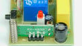
The main controller in this robot is actually at an incredible standard with a properly-designed PCB containing surface mount components and proper use of stitching via to help with power control.

The impressive controller board
The underside of the controller revealed no components but gave evidence of a well-designed PCB as well as a superb PCB manufacturer.
Cheaper products typically use low-cost PCBs that have faded solder masks, thin PCB material, and poor component legend layers. This PCB, however, shows a very thick solder mask layer, dense FR4 stock, and a clear legend.

The underside of the controller board
The IC that may be responsible for motor power control is the M2702D. While a datasheet cannot be found online, there is evidence for its role in the size of the traces that connect to the right pin and the tab which are both going to the connector that is used with the motor. Also, note the lack of a diode that was intended to be used with the motor circuit (used to remove back emf from the motor).

The motor controller (possibly a MOSFET)
Despite being “dumb” in its motion there is a controller on the robot. The microcontroller, MC81F420, is an 8-bit controller with plenty of peripherals including watchdog timers, UART, I2C, SIO, Buzzer, Timers, and PWM.

The main controller, the MC81F420

The main controller layout showing ports and peripherals. Click to enlarge
Summary
The robotic cleaner turns out to be not all that robotic. It shows a minimalist design attitude to get the item cheaper instead of using cheaper parts. This results in a product that may feel lacking in functionality yet uses good quality parts. The battery configuration was unusual but the quality of the whole unit was better than expected with a high-quality PCB and use of proper PCB design techniques.
Thanks for checking out this Teardown Tuesday! Stop in next week for another teardown!
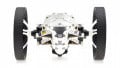
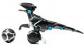
Next Teardown: The MiPoSaur Robot


Those are not lithium-ion batteries, they are NiCad, as you can see in the picture.
NiCad:
https://en.wikipedia.org/wiki/Nickel–cadmium_battery
nice thing i thought about it but i hadn’t time to do it