 Facebook
 Google
 GitHub
 Linkedin
Teardown Tuesday: Solar Powered Security Light
In this teardown, we will look at the internals of a motion-activated light which contains its own solar charging system.
In this teardown, we will look at the internals of a motion-activated light which contains its own solar charging system.
Sometimes security measures such as cameras and guards can be overkill if the item being protected is garden equipment or a few cans of gas. This is where PIR-activated lights come in, which automatically turn on upon detecting motion.
The Solar Security Light
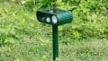
The light is designed to be mounted on a wall that has direct visibility to the sky above it. The light, itself, sits at a slight angle while the motion sensor and button sit at a much steeper angle. The solar panel sits at the top, perpendicular to the wall that the unit is mounted onto.

The solar security light

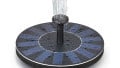
The solar panel that sits on top
The front of the unit has a button that allows for selection of options, activation, and modes. Three lights on the front indicate the current option. A PIR sensor sits on the left of the button and indicator lights.

PIR sensor, button, and indicator lights
The back of the unit contains the singular mounting hole that is used to keep the unit on the wall. The fixture method is identical to that of a picture frame which has the advantage of easy setup but the disadvantage of easily being stolen.

The fixture and screws
Removing all the screws reveals the internal parts and metal frame. The metal frame is made of thin sheet metal and was incredibly sharp (if you decide to tear down this item at home, use gloves!). For perspective, the metal was sharp enough to chop carrots!

Metal sheet that sits on the outside

Unit opened
Battery and Light
The battery included in the solar security light is a lithium ion battery which has a capacity of 2600mAh. While it advises not to short circuit, the temptation to measure the short circuit current was too great. Measurements with a multi-meter showed that, under short circuit conditions, the battery delivers 15A of current at a voltage of 3.3V (the internal resistance based on these values would be 0.22 ohms).
The solar panel, meanwhile, outputs 6V when in direct sunlight and can output close to 200mA (making this panel the 1-watt variety).

The battery in its housing

The battery removed
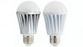
The light on the module consists of an LED array made on an FR2 PCB. The underside does not use a solder mask and shows that the PCB is single-sided.
The use of LEDs is most likely due to their excellent efficiency (as compared to standard luminaries such as halogen and tungsten lamps). Having said that, the unit only consumes measurable amounts of power when the system is activated. Therefore, even if thick clouds persists for a week, the system should still be able to operate during the night and activate the LEDs when needed.

The LED panel
The PCB
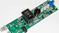
While the LED matrix is made on a low-cost PCB with a poor edge finish, the main PCB is of exceptional quality. The main PCB shows mostly surface-mount components including a 16-pin SMD IC (most likely the main controller), the PIR sensor, single tactile button, and many supporting components.

The main PCB
This part of the PCB handles power switching to the LED array which consists of SMD components (either MOSFETs or bilateral switching devices), transistors (labeled Q), and resistors.
Interestingly, there are many stitching via which are being used here to reduce the resistance of the traces (by using two sides and thick-plated holes).

The LED control components
The larger 16-pin IC has the designation 15W201S. This tells me that this is produced by the company STC Microcontroller. These microcontrollers consist of an 8051 CPU, operate up to 35MHz, many peripherals and are incredibly cheap (five can be bought for $3).

The microcontroller
The PIR sensor (labeled AL412) is a fully-enclosed system that produces an output when a change in heat source is detected. While the unit has AL412 engraved into the packaging, an identical product, the AM412 (PDF), comes up in searches. The sensor has an ADC, testing logic, and comparison system all integrated which makes creating alarm systems that trigger upon detection much easier.

The PIR sensor
The key section of the PCB is just what it is, a tactile switch: a few components such as transistors, resistors, and capacitors, and the three LED indicators for mode and arming.

The key and indicator section of the PCB
Summary
This design shows how even sensors are becoming more intelligent and easy to implement in designs, even low-cost ones. The microcontroller used in this design, while almost unknown, shows how even basic controllers are becoming more advanced. A few dollars can now get you a controller that has many timers, UART modules, SPI, I2C, ADC, and much more.
Next Teardown: 3D Printing Pen


Pls I need someone that can improve my electronics knowledge in terms of d practical , how to troubleshoot and make use of the components very well. Pls I need your WhatsApp number and your e-mail address.
My number is +2348138316315
Email is .(JavaScript must be enabled to view this email address)
Have you tried ABIS LED Panels?
https://www.abiselectronics.com/collections/led-panels
QUICK AND EASY INSTALLATION: This panel ceiling light can be built-in directly for quick installation. Convenient and elegant and easy to DIY!