Facebook
 Google
 GitHub
 Linkedin
Build an Arduino Controlled USB Power Supply
Build an Arduino controlled power supply that automatically adjusts the output to maintain a constant voltage or a constant current.
Arduinos are great for automatically controlling all kinds of circuits. In this project, I'll show a simple way that an Arduino can be used to make a power supply that automatically adjusts its output to maintain a constant voltage or a constant current. I designed this circuit to run on USB power and it is design specifically for small low voltage applications. But you can easily modify it to use a larger power supply for higher power applications.

Materials
Arduino Microcontroller
IRF510 Power MOSFET
1 kohm Resistor
470 ohm Resistor
2 x 100 kohm Resistor
10 ohm Resistor (rated for at least 2.5 watts)
1000 microfarad Capacitor
SPDT Switch
2 x Momentary Pushbutton Switch
Screw Terminal Connectors
USB Connector Cable
Jumper Wires
Powering the Circuit
Power for this project will be supplied by a USB port and routed through the Arduino. The Arduino is connected to the USB port with a standard USB connector cable. The power supply circuit that we are building will be connected to the 5V pin on the Arduino. This pin can supply 5V and up to 200mA. However, I have written the code so that the current of the power supply circuit should never go above 150mA.

The Output Circuit

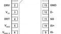
The main part of the output circuit is a transistor circuit that is built around an IR510 power MOSFET.
Pin 9 supplies a PWM signal to the circuit. This signal is sent through a 1 kohm resistor and 1000 microfarad capacitor and is smoothed out to a relatively constant DC signal (though there is still some fluctuation). This DC signal is sent to the gate of the MOSFET.
A 470 ohm resistor is connected between the gate of the transistor and 5V in order to raise the gate voltage up to a point near where the source-drain junction will conduct. These values may need to be adjusted to calibrate the circuit for the specific parts that you are using. The 1 kohm resistor and the 470 ohm resistor can be substituted with higher values. This would allow you to use a smaller value for the capacitor.
Connected to the drain of the MOSFET is a 10 ohm 10 watt reference resistor. This junction is also connected to analog pin 2 on the Arduino.
The opposite side of the 10 ohm resistor is connected to analog pin 1. This is used to sense the output of the power supply. The output terminals of the power supply are connected to the reference resistor and 5V. For easy access, I used a pair of screw terminals to connect and disconnect wires from the output.

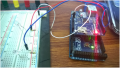
The Switches

The switches that control the circuit are mounted onto a separate breadboard for simplicity. Two momentary pushbuttons are used to adjust the output of the power supply. One end of each switch is connected to GND. The opposite end is connected digital pins 10 and 11. These digital pins are also connected to the 5V with 100 kohm resistors. These act as pull-up resistors and set the digital pins HIGH until the buttons are pressed. The third switch is a single pole double throw toggle switch. This switch sets the output mode. The two end pins of the switch are connected to GND and 5V. The center pin is connected to digital pin 12. When pin 12 is connected to 5V the system is set to output a constant voltage. When pin 12 is connected to GND the system is set to output a constant current.

The Code
At the top of the code, the first item in the declared variables is the “resistance” variable. This is the value of the reference resistor used in the circuit. You want to use a multimeter to measure this value exactly. Do not assume that it is the labeled value. This could give you inaccurate readings when you try to use your power supply. Once you have measured the resistor, write this value (in ohms) in the code.
In the first section of the main loop of code, the analogRead function is used to measure the voltage at both sides of the reference resistor. With these values, you can then calculate both the terminal voltage of the power supply and the current going through the load.
Next the digitalRead function is used to determine the state of the switches. The toggle switch sets the operating mode of the power supply. In one mode the output is set to a constant voltage. In the other mode the output is set to a constant current. If one of the momentary pushbuttons is pressed, the target output level is adjusted up or down. These functions have a built-in delay to avoid false triggering from switch bounce and to limit how quickly the output can be changed.
Next the output of the power supply is displayed with the Serial.print command. This is useful for debugging the operation of the power supply.
Built into the code are various safety limits. At startup, there is a delay to allow the output to reset before the circuit starts automatically adjusting itself. To avoid damaging the Arduino, the output is limited to 150mA. The analogWrite functions that control the outputs can never exceed 250 (on a scale of 255) and they can never go below 0. The system is also limited in how quickly the output can change.
Arduino_Controlled_Power_Supply_Code.zip
Operation
This circuit will perform fairly well in the designated operating range. It has an accuracy of about +/- 5 mA or +/- 0.05 V. The output is relatively steady, but there is still some fluctuation due to the fact that the circuit is driven by a PWM signal.

Give this project a try for yourself! Get the BOM.