 Facebook
 Google
 GitHub
 Linkedin
Timing Light Sequences: Build a Traffic Light Controller with an Arduino MEGA
Learn how to simulate a traffic light using an Arduino.
Learn how to simulate a traffic light using an Arduino.
Traffic lights are one of those things that, for most people, seem to blend into the landscape of everyday life. Wherever there are a moderate amount of cars, there will probably be one of these devices present. Modern day traffic lights are pretty complex within and have all kinds of sensors, timers, and even traffic monitoring systems that they employ to help efficiently control the rate of traffic.
Now we are not going to try to build a real traffic light, but we sure can simulate one with an Arduino! Doing this exercise is a great way to get more comfortable with Arduino’s basic and most commonly used commands. It will also help think through a problem and design logically to meet certain criteria. As a bonus, this project helps us appreciate how traffic lights work, at least at the basic functional level.
This project will implement both USA- and UK-style lights.
Bill of Materials
Hardware
- LEDs
- 2 red
- 2 green
- 2 yellow or amber
- Resistors
- 6 resistors (You can stick to around 330 to 1k ohm for each color.)
- Arduino
- MEGA (Really any kind will do, but we are using a MEGA here.)
- Soldering Iron + Solder
- Wire Cutters (for simple lead trimming)
Software
- Arduino IDE
Theory
The idea of a basic traffic light is to control the rate of traffic. As mentioned before, modern traffic lights can monitor traffic, change light cycles for pedestrians requesting to cross, know when to change its timer for increase traffic flow, etc.
For our project, we will implement a four-way intersection based on a fixed time interval for each light. That is to say that the light has no feedback and will simply run without regard to the traffic volume. Even though this is not an intelligent light, we can implement this system in an intelligent way. Perhaps even save some money doing it!
Say, for example, we have a four-way intersection whose streets are Busy Bunny Lane and Lazy Tortoise Ave (both one-way only streets). From the town’s traffic history conducted by the local police municipality, we find that Busy Bunny Lane is busier than Lazy Tortoise Ave (shocking!). Since we know the typical traffic flow of this intersection, simple timer-based control is appropriate. Adding any other features here would be a waste of money which the town cannot afford.
What we need for our simulation is a way to represent our traffic light; the LEDs will be used for this. The rest of the control and logic will be performed by the Arduino. It will serve as our intelligent controller and timer. That means it will turn each light on and off and will count the time that each one should be on.
For an added bonus, this simulated setup will have the ability to switch between the USA- and UK-style lights by changing a constant in the code. You could use a digital input to switch the operation, but that would need wire which is not listed on the bill of materials!
Loop Sequence (USA Style)
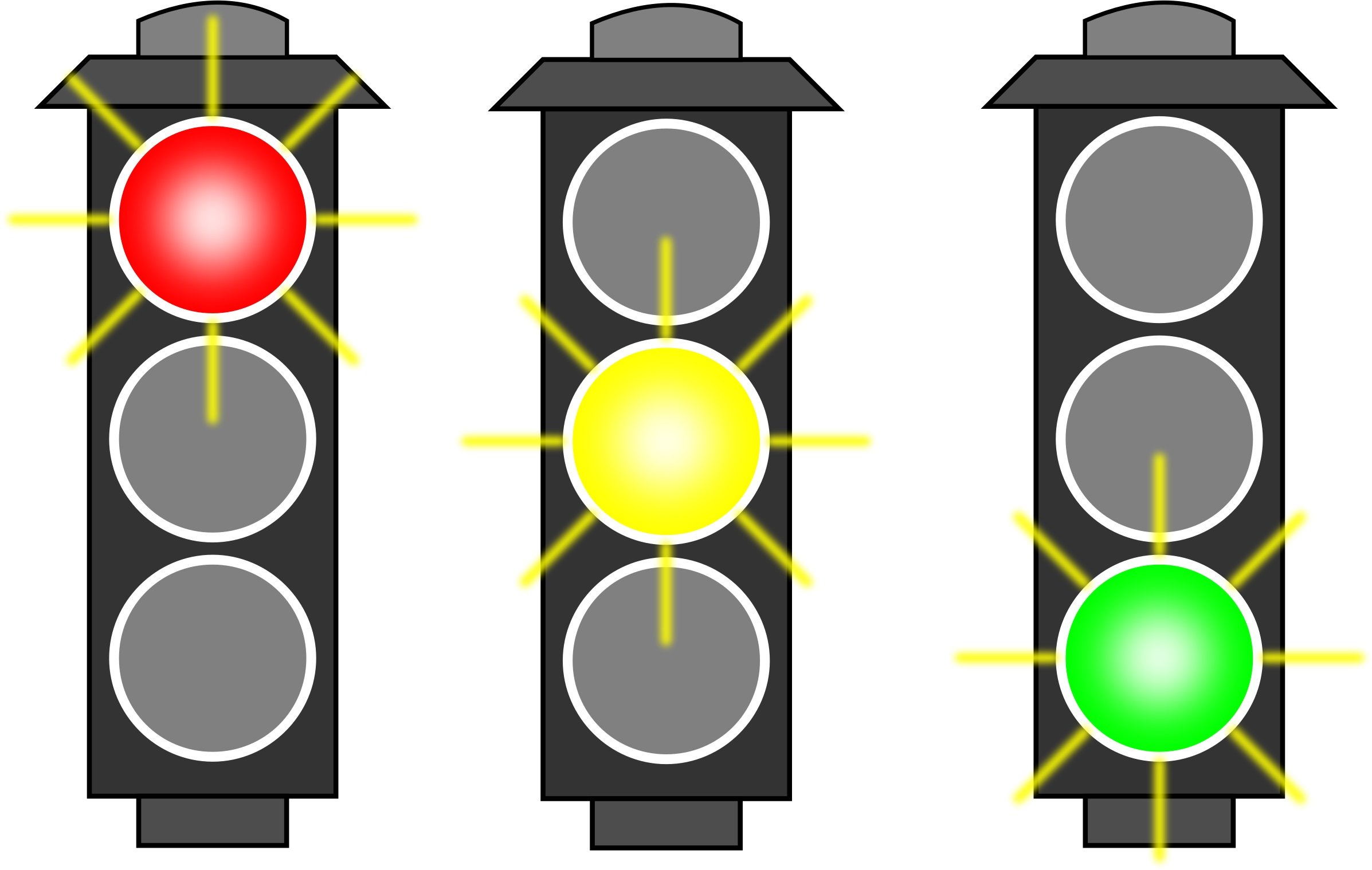
A simple USA-style traffic light consists of a red, amber, and green light. The typical sequence is as follows:
- Green (safe to proceed)
- Amber (slow down, red light soon)
- Red (stop)
This is, however, the loop for only one street. The other intersection must be thought through as well. To make this easier to illustrate, we are going to use a timing table to help us better visualize the entire loop sequence.
Let’s assume that Busy Bunny Lane has to have its green traffic light on for 12 seconds and Lazy Tortoise Ave’s green traffic light on for 4 seconds. For both streets, it is permissible to have the amber traffic light on for 3 seconds. For the red traffic lights, the green and amber cycle times will directly influence this. Study the timing table below to understand what this means.

As you can see, this makes the situation much easier to understand. It is not necessary to break it down into seconds, but for the point of example and illustration, it might be easier to digest if you are attempting something like this for the first time.
If this table is still a little unclear to you, then think about it this way: When the system is first turned on, the first row (Timeline sec = 0) is active and will continue to be active until the next elapsed second (timeline sec = 1). The light sequence in sec = 1 will be active whether the system is on 1.20 seconds or 1.99 seconds of operation. This concept spreads throughout the entire table.
The entire cycle time is 26 seconds, which means this is when both streets have had a turn to send traffic drive through their light. Once you have reached the end of the table, the entire thing starts all over again. If you look closely, there are two instances where both lights are red. Before reading on, try to think about why this design choice was made.
If you think about it carefully, if you were to have one street go red and the other immediately go green, you might have accidents. This of course depends on the size of the street, the speed limit, and other factors. But to be safe, we can assume that perhaps a person on amber for either street might not stop in time and will run the amber light while it is turning red. And if the other street is not paying attention, they might run into this person and cause an awful accident! It is much better to have both sides go red to have things “settle down” and then start from a more predictable and stable condition.
Loop Sequence (UK Style)
A simple UK-style traffic light consists of a red, amber, and green light but is slightly different than the USA style. The typical sequence is as follows:
- Green (safe to proceed)
- Amber (slow down, red light soon)
- Red (stop)
- Red / amber (stay stopped but just letting you know the light turns green soon)
So you can see it is slightly different that the USA one. Instead of an instant green, the amber light comes on with the red light to warn driver that the green light is coming really soon but please stay stopped until then. Below is the timing chart to illustrate this.

Wire it Up
The hardware part of this project is not all that complicated and does not really require a breadboard; not even a single wire!
We will first begin by wiring up the first traffic light.
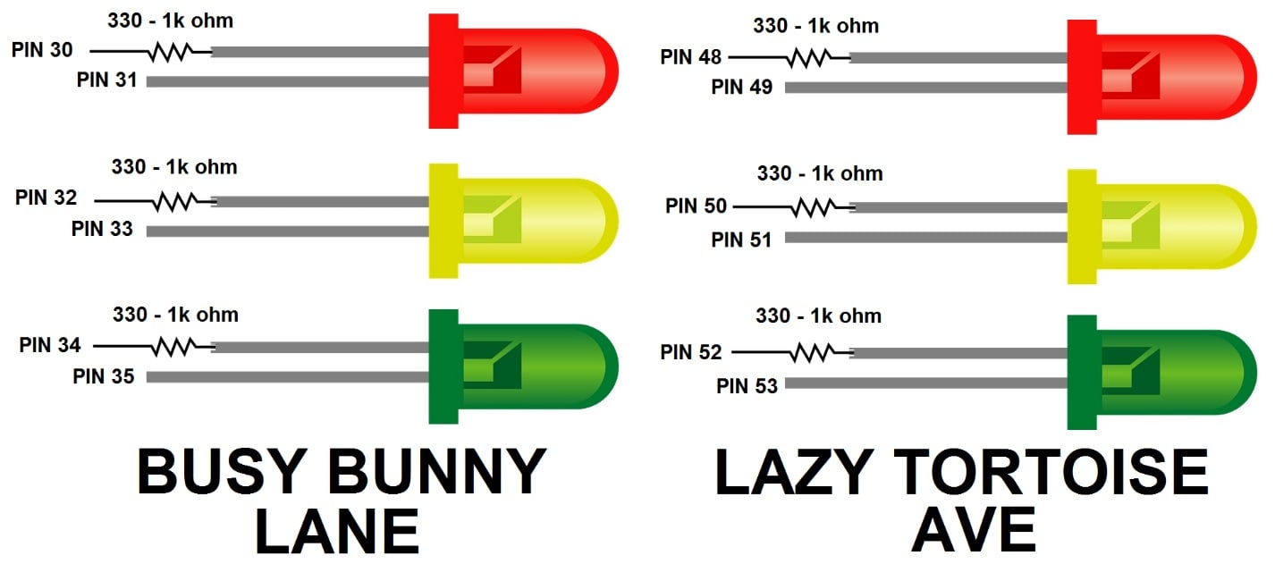
Take the positive side of a red LED and insert it into pin 31. The positive side is usually the longer lead, but if they're the same length, the flat side of the outer casing is negative.
Now take a 330 to 1k ohm resistor and insert it into pin 30.
Next, take the other end of the resistor and solder to the other end of the LED, which will be the negative side. Some trimming might be necessary for a better fit. Usually, an LED has one end wired to positive or negative of the power supply (our case that is +5V) but that would require some wire. Instead, we will use pin 30 as our ground when we set it low. Not quite common practice but for this traffic light simulation, it will do just fine! Repeat these steps again and use the chart below for a pin-to-LED mapping.
And here is how I soldered my LEDs:

Finally, it should all end up looking something like below:

And more formally, a schematic of what you are looking at:

Arduino Code
The code found here has a ton of comments and should help you along with the article. If you were to just upload this, it would cycle the light sequence immediately. To change from USA and UK style, read the comments on the top to find out! As always, if you need help with anything, a comment below or a trip to forums will do.
There is one thing to note about the code. While turning on and off outputs for the LEDs, there is a short moment that some LEDs are turned off and on extremely quickly. As you will find in the code's comments, I did this so it was easier to follow along with the timing table from earlier. For our application, the LED will look like it did not turn off at all! This is because the on-off-on transistion was so fast, that our eyes cannot pick them up. As a warning though, this code readability technique migh cause problems in other projects, like clocking a flip-flop. We cannot see it but the flip-flop will surely know the transistion has occured! But there are also times where this is taken advantage of, like when paralleling 7 segment displays. Most that you see have each digit turn on one at a time but we never realize it. In our case for the traffic light it does not help nor hurt us, so I just let it be.
/*
================================================================================

    File........... Traffic Light Controller Test Code
    Purpose........ To simulate basic USA and UK style traffic lights
    Author......... Joseph Corleto
    E-mail......... corleto.joseph@gmail.com
    Started........ 06/11/2016
    Finished....... 06/11/2016
    Updated........ --/--/----

================================================================================
   Notes
================================================================================
- Please visit www.allaboutcircuits.com to search for complete article!

================================================================================
  Updates
================================================================================
*/

//===============================================================================
//  Header Files
//===============================================================================

//===============================================================================
//  Constants
//===============================================================================
const int TRAFFIC_LIGHT_STYLE   = 1;  // Used to pick the style traffic light
const int GREEN_LIGHT           = 12; // Green light time in seconds
const int AMBER_LIGHT           = 3;  // Amber light time in seconds
const int DEAD_LIGHT            = 2;  // Dead light time in seconds
const int RED_AMBER_LIGHT       = 1;  // Red/Amber light time in seconds

// I know what you are thinking, why the defaut values? It becomes clearer
// later on in the code. I basically compute Lazy Tortoise Ave's cycle from
// the cycle times from Busy Bunny Lane's values. Keep reading!

//===============================================================================
//  Variables
//===============================================================================

//===============================================================================
//  Pin Declarations
//===============================================================================
//Inputs:
// You could put in a switch to go back and forth to usa and uk modes if
// are feeling ambitious!

//Outputs:
int greenBusyBunnyLane      = 30;    // Green light output: Busy Bunny Lane
int amberBusyBunnyLane      = 32;    // Amber light output: Busy Bunny Lane
int redBusyBunnyLane        = 34;    // Red light output: Busy Bunny Lane

int greenBusyBunnyLaneGnd   = 31;    // Green light ground: Busy Bunny Lane
int amberBusyBunnyLaneGnd   = 33;    // Amber light ground: Busy Bunny Lane
int redBusyBunnyLaneGnd     = 35;    // Red light ground: Busy Bunny Lane

int greenLazyTortoiseAve    = 48;    // Green light output: Lazy Tortoise Ave
int amberLazyTortoiseAve    = 50;    // Amber light output: Lazy Tortoise Ave
int redLazyTortoiseAve      = 52;    // Red light output: Lazy Tortoise Ave

int greenLazyTortoiseAveGnd = 49;    // Green light ground: Lazy Tortoise Ave
int amberLazyTortoiseAveGnd = 51;    // Amber light ground: Lazy Tortoise Ave
int redLazyTortoiseAveGnd   = 53;    // Red light ground: Lazy Tortoise Ave

//===============================================================================
//  Initialization
//===============================================================================
void setup()
{
  // Set appropriate pin light outputs for Busy Bunny Lane
  pinMode(greenBusyBunnyLane, OUTPUT);
  pinMode(amberBusyBunnyLane, OUTPUT);
  pinMode(redBusyBunnyLane, OUTPUT);

  pinMode(greenBusyBunnyLaneGnd, OUTPUT);
  pinMode(amberBusyBunnyLaneGnd, OUTPUT);
  pinMode(redBusyBunnyLaneGnd, OUTPUT);

  // Set appropriate pin light outputs for Lazy Tortoise Ave
  pinMode(greenLazyTortoiseAve, OUTPUT);
  pinMode(amberLazyTortoiseAve, OUTPUT);
  pinMode(redLazyTortoiseAve, OUTPUT);

  pinMode(greenLazyTortoiseAveGnd, OUTPUT);
  pinMode(amberLazyTortoiseAveGnd, OUTPUT);
  pinMode(redLazyTortoiseAveGnd, OUTPUT);

  // Set initial states
  digitalWrite(greenBusyBunnyLane,LOW);
  digitalWrite(amberBusyBunnyLane,LOW);
  digitalWrite(redBusyBunnyLane,LOW);

  digitalWrite(greenBusyBunnyLaneGnd,LOW);
  digitalWrite(amberBusyBunnyLaneGnd,LOW);
  digitalWrite(redBusyBunnyLaneGnd,LOW);

  digitalWrite(greenLazyTortoiseAve,LOW);
  digitalWrite(amberLazyTortoiseAve,LOW);
  digitalWrite(redLazyTortoiseAve,LOW);

  digitalWrite(greenLazyTortoiseAveGnd,LOW);
  digitalWrite(amberLazyTortoiseAveGnd,LOW);
  digitalWrite(redLazyTortoiseAveGnd,LOW);
}

//===============================================================================
//  Main
//===============================================================================
void loop()
{
  // The program needs to know which traffic light style to use. Fortunately,
  // at the top of this program, under Constants, we reserved TRAFFIC_LIGHT_STYLE
  // for this very purpose. Now we can just use the SWITCH-CASE conditional
  // statements below to choose which one to execute for the life of this
  // program. You can always add more as well if you would like!
  switch (TRAFFIC_LIGHT_STYLE)
  {
    case 0:
      usaTrafficLight();
      break;

    case 1:
      ukTrafficLight();
      break;

    default:
      break;
  }
}

//===============================================================================
//  Functions
//===============================================================================
/////////////////////
// usaTrafficLight //
/////////////////////
void usaTrafficLight()
{
  // Remember to consult allaboutcircuits.com for the timing table! This will
  // be really helpful in figuring out why the code exists below. Now this is
  // only one way of making this whole cycle happen. When I code, I like to
  // make everything as readable as possible. And if I do not need the extra
  // computing speed, I will re-introduce statements for the sake of remembering
  // what the last condition was. So if you think to yourself "hey, he turned
  // on the red light, then off, and then on!", you are right! I just wanted
  // to make things easier to read!

  // First have Busy Bunny Lane have its green light on. And according to the
  // chart, Lazy Tortoise Ave is Red. I will be using FOR LOOPs in one second
  // increments since this will help maintain logical continuty from the timing
  // table. Do not forget to turn the lights off after each cycle!
  for (int seconds = 0; seconds < GREEN_LIGHT; seconds++)
  {
    digitalWrite(greenBusyBunnyLane,HIGH);
    digitalWrite(redLazyTortoiseAve,HIGH);
    delay(1000);
  }
    digitalWrite(greenBusyBunnyLane,LOW);
    digitalWrite(redLazyTortoiseAve,LOW);

  // Now that the green light time has elapsed for Busy Bunny Lane, we can
  // move onto our amber light time.
  for (int seconds = 0; seconds < AMBER_LIGHT; seconds++)
  {
    digitalWrite(amberBusyBunnyLane,HIGH);
    digitalWrite(redLazyTortoiseAve,HIGH);
    delay(1000);
  }
    digitalWrite(amberBusyBunnyLane,LOW);
    digitalWrite(redLazyTortoiseAve,LOW);

  // Dead zone up ahead to prevent our traffic accidents.
  for (int seconds = 0; seconds < DEAD_LIGHT; seconds++)
  {
    digitalWrite(redBusyBunnyLane,HIGH);
    digitalWrite(redLazyTortoiseAve,HIGH);
    delay(1000);
  }
    digitalWrite(redBusyBunnyLane,LOW);
    digitalWrite(redLazyTortoiseAve,LOW);

  // Finally Lazy Tortoise Ave gets its turn for green!
  for (int seconds = 0; seconds < (GREEN_LIGHT / 3); seconds++)
  {
    digitalWrite(redBusyBunnyLane,HIGH);
    digitalWrite(greenLazyTortoiseAve,HIGH);
    delay(1000);
  }
    digitalWrite(redBusyBunnyLane,LOW);
    digitalWrite(greenLazyTortoiseAve,LOW);

  // Lazy Tortoise Ave now goes into amber light.
  for (int seconds = 0; seconds < AMBER_LIGHT; seconds++)
  {
    digitalWrite(redBusyBunnyLane,HIGH);
    digitalWrite(amberLazyTortoiseAve,HIGH);
    delay(1000);
  }
    digitalWrite(redBusyBunnyLane,LOW);
    digitalWrite(amberLazyTortoiseAve,LOW);

  // Once again, a dead zone
  for (int seconds = 0; seconds < DEAD_LIGHT; seconds++)
  {
    digitalWrite(redBusyBunnyLane,HIGH);
    digitalWrite(redLazyTortoiseAve,HIGH);
    delay(1000);
  }
    digitalWrite(redBusyBunnyLane,LOW);
    digitalWrite(redLazyTortoiseAve,LOW);

  // Cycle is over!
}

////////////////////
// ukTrafficLight //
////////////////////
void ukTrafficLight()
{
  // This will be very similar to the usaTrafficLight

  // First have Busy Bunny Lane have its green light on. And according to the
  // chart, Lazy Tortoise Ave is Red. I will be using FOR LOOPs in one second
  // increments since this will help maintain logical continuty from the timing
  // table. Do not forget to turn the lights off after each cycle!
  for (int seconds = 0; seconds < GREEN_LIGHT; seconds++)
  {
    digitalWrite(greenBusyBunnyLane,HIGH);
    digitalWrite(redLazyTortoiseAve,HIGH);
    delay(1000);
  }
    digitalWrite(greenBusyBunnyLane,LOW);
    digitalWrite(redLazyTortoiseAve,LOW);

  // Now that the green light time has elapsed for Busy Bunny Lane, we can
  // move onto our amber light time.
  for (int seconds = 0; seconds < AMBER_LIGHT; seconds++)
  {
    digitalWrite(amberBusyBunnyLane,HIGH);
    digitalWrite(redLazyTortoiseAve,HIGH);
    delay(1000);
  }
    digitalWrite(amberBusyBunnyLane,LOW);
    digitalWrite(redLazyTortoiseAve,LOW);

  // Dead zone up ahead to prevent our traffic accidents.
  for (int seconds = 0; seconds < DEAD_LIGHT; seconds++)
  {
    digitalWrite(redBusyBunnyLane,HIGH);
    digitalWrite(redLazyTortoiseAve,HIGH);
    delay(1000);
  }
    digitalWrite(redBusyBunnyLane,LOW);
    digitalWrite(redLazyTortoiseAve,LOW);

  // Here is where the uk light differs!
  for (int seconds = 0; seconds < RED_AMBER_LIGHT; seconds++)
  {
    digitalWrite(redBusyBunnyLane,HIGH);
    digitalWrite(redLazyTortoiseAve,HIGH);
    digitalWrite(amberLazyTortoiseAve,HIGH);
    delay(1000);
  }
    digitalWrite(redBusyBunnyLane,LOW);
    digitalWrite(redLazyTortoiseAve,LOW);
    digitalWrite(amberLazyTortoiseAve,LOW);

  // Finally Lazy Tortoise Ave gets its turn for green!
  for (int seconds = 0; seconds < (GREEN_LIGHT / 3); seconds++)
  {
    digitalWrite(redBusyBunnyLane,HIGH);
    digitalWrite(greenLazyTortoiseAve,HIGH);
    delay(1000);
  }
    digitalWrite(redBusyBunnyLane,LOW);
    digitalWrite(greenLazyTortoiseAve,LOW);

  // Lazy Tortoise Ave now goes into amber light.
  for (int seconds = 0; seconds < AMBER_LIGHT; seconds++)
  {
    digitalWrite(redBusyBunnyLane,HIGH);
    digitalWrite(amberLazyTortoiseAve,HIGH);
    delay(1000);
  }
    digitalWrite(redBusyBunnyLane,LOW);
    digitalWrite(amberLazyTortoiseAve,LOW);

  // Once again, a dead zone
  for (int seconds = 0; seconds < DEAD_LIGHT; seconds++)
  {
    digitalWrite(redBusyBunnyLane,HIGH);
    digitalWrite(redLazyTortoiseAve,HIGH);
    delay(1000);
  }
    digitalWrite(redBusyBunnyLane,LOW);
    digitalWrite(redLazyTortoiseAve,LOW);

  // Here is where the uk light differs, again!
  for (int seconds = 0; seconds < RED_AMBER_LIGHT; seconds++)
  {
    digitalWrite(redBusyBunnyLane,HIGH);
    digitalWrite(amberBusyBunnyLane,HIGH);
    digitalWrite(redLazyTortoiseAve,HIGH);
    delay(1000);
  }
    digitalWrite(redBusyBunnyLane,LOW);
    digitalWrite(amberBusyBunnyLane,LOW);
    digitalWrite(redLazyTortoiseAve,LOW);

  // Cycle is over!
}
Possible Next Steps
If you want to expand this project, you may want to consider buying a real traffic light and wiring it up! But of course, you would need to be comfortable working with mains voltage (e.g., ~120 VAC in the United States). And if you are not, DO NOT THINK ABOUT IT! You would need something called a relay. To learn about relay construction, I would suggest starting here.
And where to find an actual traffic light to play with? Best sources I have seen are eBay, garage/yard sales, flea markets, and antique shops. So if you happen to find one for sale at a reasonable price (depends on market demand but for typical plastic ones, $25 to $100), grab one, make it work with the guidance of this article, and presto, a great conversation piece for your guests!
Now of course, all of this effort in learning how to sequence and time lights doesn't have to stop with a traffic light. You could just as easily use this setup to time Christmas lights or for simple stage lighting effects. You can still use a timing table to aid in the whole process. You could also use this as a crude timer for turning on and off things that have a significantly longer delay, like a patio light or a pool pump. Basically, something that needs to work around a certain timetable but not exact. Hopefully, this opens your imagination to other things beyond traffic lights.
Have fun!
Give this project a try for yourself! Get the BOM.
Traffic_Light_Controller_Test_Code.zip


Thank you for that nice DIY experiment.
One remark form my side :
Who can i simulate the GND using a Uno R3 with that dozen pin´s 😊.
There are not enough pin´s to set one pin per light as a GND.
For now i start with the BusyBunnyLane (german traffic jam)
Many thanks for a tip how to proceed
Regards