 Facebook
 Google
 GitHub
 Linkedin
Build Programmable Time-based Switches Using a Real Time Clock
Use DS3231M RTC alarm functions to make programmable, time-based, switches to power devices on and off at precise times.
Use DS3231M RTC alarm functions to make programmable, time-based, switches to power devices on and off at precise times.
Constructing a Basic DS3231M Board
Often overlooked, real time clock alarms can be used to switch power to external circuits at precise times. They can also be used to power external circuits for only as long as needed, making battery operation possible in many situations. This project shows how to construct and program a DS3231M RTC as a power cycle switch. The approach can also be extended to a variety of external circuits to control battery power.
A real time clock (RTC) is an electronic time keeping device commonly available as a single integrated circuit. Typically, these circuits include a power backup capability to retain the time while power is off to the main circuits. It is common to see these chips incorporated into computer motherboards or any appliance requiring access to the time. The low-price, availability and relative accuracy of these chips, however, make them a desirable addition to many microcontroller projects. While their major function is simple time and date keeping, some RTC chips also have programmable alarm functions. This project explores the use of these alarm functions to implement programmable, time-based, switches. The advantage of this method is that power to a device can be applied at precise times, and only for as long as needed, which is desirable for battery operation.
Not all RTC chips have alarm functions but a few that do are the DS3231 (Maxim Integrated), MCP79410 (Microchip) and ISL12026 (Intersil). Here, a DS3231M is used to construct a simple, but fully functional, RTC building block and, further, to construct an example RTC-based switch. The DS3231M has a number of features that make it an attractive choice. These include; relatively high precision, I2C communications, an integrated resonator and easy battery backup. The RTC also contains software trimming for specific temperature compensation and even an on-chip temperature sensor.
The example presented also uses an Arduino UNO board with software written specifically to facilitate programming the alarms. The general concept, and the circuits presented, however, can be easily adapted for use with any microcontroller system using I2C communications.

Prototype basic DS3231M RTC circuit board.
Figure 1 presents a schematic for the basic RTC circuit that can be used as the building block for a time-based switch. Essentially, it is a simple break-out board that will allow connections to and from the RTC. The DS3231M used is packaged as an 8-pin surface mount device. For bread boarding and prototyping it is convenient to use a carrier board which requires some fairly detailed soldering, but that is probably the most difficult part of the project construction. Apart from the DS3231M, the circuit has only a few other components and is a fully functional I2C RTC that can be used with many microcontrollers.

Figure 1. Schematic for the basic RTC board.
| Part | Description |
|---|---|
| RTC1 | DS3231M |
| C1,C2 | 0.01 uf capacitor |
| R1,R2 | 10K resistor |
| J1 | 5-pin jumper/header |
Resistors R1 and R2 serve as pull-up resistors for the I2C communication lines. If you already have pull-up resistors on the I2C lines on your system, their value may need to be changed or they may need to be eliminated completely. BAT1 is the critical 3v back-up battery that keeps the RTC running. A CR2025 is shown but other 3v non-rechargeable batteries can also be used, such as the CR2032. C1 is the typical by-pass capacitor to minimize power supply fluctuations. C2 is not strictly necessary, but is recommended when the battery is a main source of power to the RTC.
JP1 is where connections are made to either the Arduino UNO for programming or to the final switching circuit. For the Arduino use the connections in the following table.
| JP1 | Arduino |
|---|---|
| Vcc | 5v or 3.3v |
| SCL | A5 or SCL |
| SDA | A4 or SDA |
| GND | GND |
| ALARM | not connected |
The DS3231M operates as a slave I2C device with a fixed address of 0x68. Essentially, the DS3231M appears to the master (Arduino UNO in this case) as a 19 byte memory array. Those 19 bytes are used to read and write to the internal registers. It is advantageous to become somewhat familiar with the data sheet for the device before attempting to program the functions.
The 19 internal registers are organized into three major groups; time and date, alarms, and miscellaneous – including control and status. Again, familiarity with the chip’s data sheet will provide all of the details, but the table below presents a general summary.
| Address | Functions |
|---|---|
| 0x00-0x06 | Time and Date |
| 0x07-0x0d | Alarm 1 and Alarm 2 |
| 0x0e-0x12 | Control/Status/Aging/Temperature |
DS3231M Alarms
Pin 3, called SQW/INT, is the alarm output. The pin is multifunction and can be programmed to either output a square wave or as an alarm. As an alarm, it is an active low, open drain output. To use an alarm function, attach an external pull up resistor tied to a voltage source not exceeding 5.5 volts. The source can be separate from the chip’s Vcc or battery line, as long as the grounds are connected.
There are two independent sets of alarm registers and either one can trigger an alarm. When an alarm occurs, the SQW/INT pin will change states and that change will serve as a signal to other circuitry that forms the basis of using the RTC as a programmable switch. When an alarm is asserted, it will stay asserted until a flag is reset in one of the internal registers of the DS3231M. Thus, external circuitry needs to be able to write to the DS3231M to turn off the alarm.
An alarm can be programmed to occur when there is a match between certain alarm registers and certain time registers according to specific alarm register configurations. Alarm #1 can be configured to trigger when there is a match on; 1) seconds, 2) minutes and seconds, 3) hours, minutes and seconds, 4) date, hours, minutes, and seconds, 5) day, hours, minutes, and seconds, or 6) every second. Alarm #2 can be configured to trigger when there is a match on; 1) minutes, 2) hours and minutes, 3) date, hours and minutes, 4) day, hours, and minutes, or 5) every minute.
A DS3231 Software Tool
Owing to its popularity, there are several Arduino libraries and many code examples available to use with the DS3231 and the basic board in figure 1 should work well with those libraries and code examples. Some of the libraries support only basic time of day functions while others are quite comprehensive and are designed around system-wide RTC functions.
Included with this article is an Arduino program to specifically serve as a tool to facilitate design and testing of RTC programmable switches. In this regard, its use is a bit different than the usual Arduino sketches in that all of the DS3231 registers can be manipulated through a series of #define statements at the beginning of the program as illustrated below.
//****************************************************************************************
// USER PROGRAMMING STARTS HERE
//****************************************************************************************
//      *** No error checking is done so respect the format and value ranges ***
//
// Section 1 - clock
// SET_CLOCK YES/NO if Yes than values in section 1 will be written to the clock
#define SET_CLOCK NO        // YES/NO
#define SECONDS 0           // 0-59
#define MINUTES 0           // 0-59
// if CLOCK24 is YES than AMPM is skipped
#define CLOCK24 NO          // YES/NO for 24/12 if NO set AMPM
#define AMPM PM             // AM/PM AM=0 PM=1 (will not have effect if CLOCK24 is YES)
#define HOURS 1             // 0-23 if Clock is 24 or 1-12 if Clock is 12h
#define DAY 7               // 1-7 1=Sunday
#define DATE 1              // Day of the Month 1-31
#define MONTH 1             // 1-12
#define YEAR 16             // 00-99
//
// Section 2 - Alarm #1
// SET_ALARM1 YES/NO if Yes than all enabled values in section 2 will be written to the clock
// after setting values - alarm #1 must be enabled in Section 4
#define SET_ALARM1  NO      // YES/NO
#define A1SECOND 0          // 00-59
#define A1MINUTE 0          // 00-59
// if A1CLOCK24 is YES than A1AMPM is skipped
#define A1CLOCK24 YES       // YES/NO for 24/12 if NO set A1AMPM
#define A1AMPM PM           // AM/PM AM=0 PM=1 (will not have effect if A1CLOCK24 is YES)
#define A1HOUR 00           // 00-23 if Clock is 24 or 1-12 if Clock is 12h
#define A1DYDT YES          // YES=Day (DoW) No=Date (DoM)
#define A1DAYDATE 1         // If A1DYDT=YES then range is 1-7 (DoW)/ If NO then range is (1-31 DoM)
#define A1MASK  3           // 0-4 as described below
// 4 = Alarm once per second
// 3 = Alarm when seconds match
// 2 = Alarm when minutes and seconds match
// 1 = Alarm when hours, minutes and seconds match
// NOTE the next two depend on A1DYDT
// 0 = If A1DYDT=NO then Alarm when date, hours, minutes and seconds match
//     If A1DYDT=Yes then Alarm when day, hours, minutes and seconds match
//
// Section 3 - Alarm #2
// SET_ALARM2 YES/NO if Yes than all enabled values in section 3 will be written to the clock
// after setting values - alarm #2 must be enabled in Section 4
#define SET_ALARM2 NO       // YES/NO
#define A2MINUTE 0          // 00-59
// if A2CLOCK24 is YES then A2AMPM is skipped
#define A2CLOCK24 YES       // YES/NO for 24/12 if NO set A1AMPM
#define A2AMPM PM           // AM/PM AM=0 PM=1 (will not have effect if A2CLOCK24 is YES)
#define A2HOUR 00           // 00-23 if Clock is 24 or 1-12 if Clock is 12h
#define A2DYDT YES          // YES=Day (DoW) No=Date (DoM)
#define A2DAYDATE 1         // If A2DYDT=YES then range is 1-7 (DoW)/ If NO then range is (1-31 DoM)
#define A2MASK  0           // 0-3 as described below
// 3 = Alarm once per minute (00 seconds of every minute)
// 2 = Alarm when minutes match
// 1 = Alarm when hours, minutes match
// NOTE the next two depend on A2DYDT
// 0 = If A2DYDT=NO then Alarm when date, hours and minutes match
//     If A2DYDT=Yes then Alarm when day, hours and minutes match
//
// Section 4 - Control
#define EOSCENABLE YES      // YES/NO if YES, enables EOSC If NO, it is skipped
#define EOSCDISABLE NO      // YES/NO if YES disable EOSC If NO, it is skipped
                            // EOSC Should always be enabled to keep time using a battery
#define ENABLE32KHZ NO      // YES/NO Enable 32KHZ output pin signal
#define DISABLE32KHZ YES    // YES/NO Disable 32KHZ output pin signal
#define ENABLEBBSQW NO      // YES/NO Enable BBSQW output pin signal [battery backed] when INTC=0
#define DISABLEBBSQW YES    // YES/NO Disable BBSQW output pin signal [battery backed] when INTC=0
#define CLEARA1F NO         // YES/NO Clears the Alarm 1 interrupt flag
#define CLEARA2F NO         // YES/NO Clears the Alarm 2 interrupt flag
#define INTCNINT YES        // YES/NO SETS the INT/SQW pin to interrupt output
#define INTCNSQW NO         // YES/NO Sets the INT/SQW pin to square wave output
#define A1ENABLE NO         // YES/NO if YES Alarm 1 interrupts are enabled, if NO disabled
#define A2ENABLE NO         // YES/NO if YES Alarm 2 interrupts are enabled, if NO disabled
// Miscellaneous
#define SET_AGING NO        // YES/NO sets aging offset defined below
#define AGINGOFFSET 0       // range is -127 to +127 Positive values slow the clock (see data sheet)
#define REQCONV NO          // YES/NO if Yes, requests a temperature conversion
#define CLEAROSF NO         // YES/NO if Yes, resets the OSF flag. If no then no action
//
#define SCNUPDATE 20000     // Screen update frequency in ms
//****************************************************************************************
// USER PROGRAMMING ENDS HERE
//****************************************************************************************
That is, you can modify the registers by changing the values in the #define statements and then executing the sketch. After the registers are modified according to the #define statements, the program outputs current values to the screen at regular intervals so that you can observe changes in register values. Two characteristics of this approach are noteworthy. First, when you change values, for example the time, be sure that you do not save the sketch requesting those values be changed or the next time you run the sketch you will reprogram those same values. In some cases, like time setting, there is a #define to change or skip a change. Second, remember that after downloading a sketch to the Arduino, it will remain in the board and will execute each time that power is applied. Thus, it is a good idea to remove/replace the sketch from the Arduino once it has been used to set the desired register values.
A Power Cycle Switch

Prototype power cycle switch board.
As an example to illustrate the approach, figure 2 presents a schematic for a simple circuit that combined with the DS3231M board, will power cycle a device at a programmed time. I actually use this circuit to power cycle my router every night at 3:35 AM.
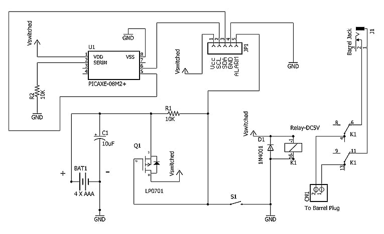
Figure 2. Schematic for the power cycle switch circuit.
| Part | Description |
|---|---|
| BAT1 | 4 X AAA battery pack (alkaline or NiMH) |
| Q1 | LP0701N P-channel MOSFET transistor |
| U1 | PICAXE 08M2+ |
| K1 | DPDT 5v DC Relay (Axicom) |
| R1,R2 | 10K resistor |
| C1 | 10 uf polarized capacitor |
| D1 | 1N4001 diode |
| JP1 | 5 pin jumper/header |
| CN1 | 2 pin connector |
| J1 | barrel jack |
| S1 | momentary switch |
Circuit Operation
My router is powered by a typical 12V DC wall wart power supply and instead of connecting the DC output directly to the router, it is connected to J1. CN1 connects to a barrel plug which goes into the router. K1 is a double pole, double throw relay with the normally closed contacts carrying the 12v DC power straight through from J1 to CN1 and to the router – take care to check that the polarity is preserved. Thus, power is normally applied to the router as usual when the relay is not energized. JP1 connects with the DS3231M board to utilize the ALARM, GND, SCL and SDA signals. Power from the battery pack goes to the source of the MOSFET and to R1. The other side of R1 goes to both the ALARM pin on JP1 and the gate of the MOSFET. When no alarm is asserted, the gate to source voltage difference is zero and no power is drawn from the battery pack. When an alarm occurs, gate to source voltage on the MOSFET exceeds the threshold and the MOSFET turns “on” – power from the battery pack will be applied to the points that I am calling “Vswitched”. When this occurs, the relay coil energizes and breaks the connections from the external power to the router.
The PICAXE 08M2+ is also powered by Vswitched and is powered when an alarm occurs. Because the alarm signal on the DS3231M persists until a flag in an internal register is cleared, we need to communicate with the RTC through the I2C interface to reset the interrupt flag and, thus, turn off Vswitched. The 08M2+ is a most inexpensive and easy solution to execute that function. The PICAXE is programmed with the simple lines below to accomplish the task. The program simply waits for 10 seconds and then communicates with the DS3231M to turn off the alarm interrupt flag which disables "Vswitched". The relay coil then returns to the resting state and power to the router is restored.
hi2csetup I2CMASTER, 010000, i2cslow, i2cbyte

main:
; make sure there was an interrupt from Alarm 1
	hi2cin $0f,(b1)
	let b2=b1 AND 000001 ; A1F is bit 0
	if b2=1 then goto shutdown
; trap a false trigger or other bug
FalseTrigger:
;put error code here if desired
shutdown:
	pause 10000
; now clear the RTC flag A1F
      let b2=b1 AND 111110
      hi2cout $0f,(b2)
      pause 10
here:
; we have powered off and should not get here
      goto here
“Vswitched” is also connected to Vcc on JP1 to connect to the RTC board. This is necessary to provide power to the RTC and pull-up resistors required for I2C communications since the PICAXE is using the I2C lines to communicate with the DS3231M. Note that if you did not use I2C pull-up resistors from the RTC board (because they were already present in your system), they will need to be included on the power cycle board. The momentary switch, when depressed, allows for manual operation of the circuit by forcing a GND connection to the gate of the LP0701N.
As simple as the circuit is, the maximum ratings of the components still need to be considered. The maximum voltage on the alarm pin is 5.5v. The LP0701N has a maximum gate to source voltage of 10v and can switch 500 mA continuously. The relay contacts are rated for 3A and the 08m2+ maximum voltage is 5.5v. The battery pack will provide 5v or 4.8v depending on whether you use alkaline or NiMh cells. While it is important to examine all of the minimum and maximum ratings of all of the components, this quick check shows that we are within some key rated limits.
We can also generate a very conservative estimate of the battery life that we can anticipate. If we assume that the batteries have an 800 mAh rating (as is typical of AAA NiMh cells) and that the circuit draws 200 mA when active (it is actually much less), we get 4 hours. We can reduce that value by 30% because nothing works out exactly according to specifications and we get 2.8 hours or 10,080 seconds. Divide that time by 10 (the number of seconds that the circuit operates per day) and we arrive at 1,008, 10-second operations. That translates into well more than 2 years. Although theoretical, that figure is impressive and illustrates the value of the technique.

The completed power cycle switch project ready for use.
Programming the Circuit
Referring back to the #define statements in the included Arduino sketch, the steps required to program the DS3231M board to configure the circuit operation follow. Again, familiarity with the DS3231M data sheet will facilitate understanding these steps. For brevity, it is assumed that you have already set the correct time on the RTC – although you can use the program to do that as well. It also assumes that other default values in the sketch are in effect at the start.
1. Connect the RTC board to the Arduino.
2. Program Alarm 1 time match registers for 3:35 AM – simply 3:35 for 24-h timekeeping.
// Section 2 - Alarm #1
#define SET_ALARM1  YES          // YES/NO
#define A1SECOND 0               // 00-59
#define A1MINUTE 35              // 00-59
// if A1CLOCK24 is YES than A1AMPM is skipped
#define A1CLOCK24 YES            // YES/NO for 24/12 if NO set A1AMPM
#define A1HOUR 03                // 00-23 if Clock is 24 or 1-12 if Clock is 12h
#define A1MASK  1                // 0-4 as described below
// 1 = Alarm when hours, minutes and seconds match
3. Program the SQW/INT pin for interrupt output (alarm).
#define INTCNINT YES // YES/NO SETS the INT/SQW pin to interrupt output
4. Enable Alarm 1 interrupts.
#define A1ENABLE YES // YES/NO if YES Alarm 1 interrupts are enabled, if NO disabled
5. Compile and download the sketch to the Arduino UNO. This will program the RTC board as desired and should produce output similar to the screen capture below. Remember that until you change the loaded program it will execute that sketch every time you power up the Arduino UNO.
6. Remove power, detach the RTC board from the Arduino and attach it to the power cycle circuit. Plug the router power supply into the jack on the circuit and attach the plug from the circuit to the router, making certain that you preserve the correct polarity of the power connections. The router should now power up normally but every day at 3:35 AM, it will turn off for 10 seconds and then back on.

Screen output from the Arduino UNO sketch after setting the register values for the power cycle switch.
Extending the Approach
The power cycle circuit presented is specialized and, some could argue, a bit of overkill. The basic approach, however, is very flexible and can be expanded in both hardware and software. Some prospects and considerations for enhancement and extension follow.
Hardware Extension. In the power cycle circuit, battery power is switched to directly operate the relay and PICAXE. We can also switch the battery power to a voltage regulator to produce a regulated voltage output to run an external controller and related circuitry. Figure 3 presents a schematic illustrating the approach.
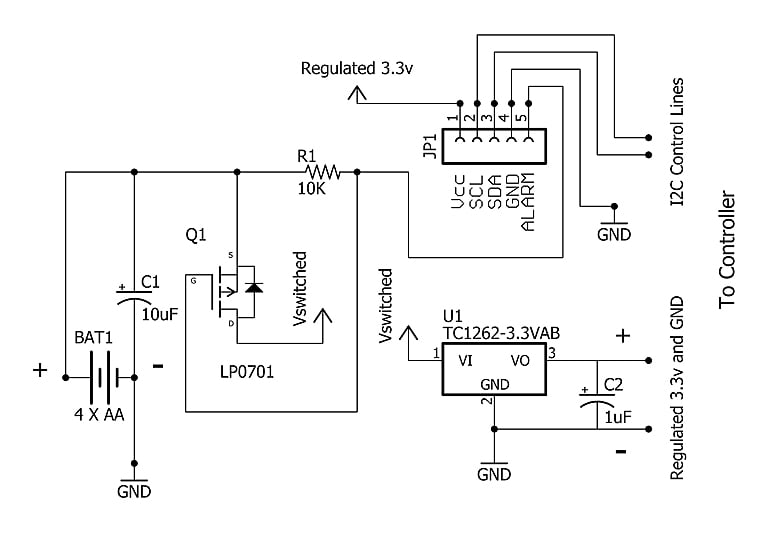
Figure 3. Schematic for using an LDO regulator with RTC alarms.
In this case, we can increase power capabilities by replacing the AAA battery pack with AA batteries or one of the popular USB rechargeable battery “sticks” – just as long as we keep the voltage to the maximum limit of 5.5v at the alarm pin. When an RTC alarm is asserted, battery power is switched to the input of a 3.3v LDO voltage regulator (e.g., TC1262) to provide a regulated output of 3.3v at up to 500 mA. For example, the regulated output can be used to power a wireless microcontroller, like the popular ESP8266, that can use battery power for short intervals to read a sensor array and transmit the readings. After transmission, the circuit can shut power off by sending the appropriate code to the DS3231M through the I2C interface. The 3.3v regulated output is also connected to Vcc of the RTC board to drive the DS3231M and pull-up resistors during I2C communication.
Software extension. The power cycle circuit represents one of the simplest uses of the RTC alarm capabilities – a single alarm daily. The DS3231M, however, has two independent alarms and they can be used in a complementary fashion. The controller software can also easily determine which alarm has fired by looking at the alarm flag bits in the DS3231M status register (address 0x0f). Even more complex alarms intervals can be implemented, however, because the controller can program the DS3231M alarms dynamically. For example, when an alarm occurs, the controller can read the time and program the occurrence of the next alarm depending upon the time of day or according to a preset schedule. In this manner, virtually any alarm interval and sequence of intervals can be implemented, making the approach capable of meeting the most specific and demanding of timing requirements.
Closing Thoughts
The alarm functions of RTC circuits are often overlooked. This article has examined the alarm feature of the DS3231M RTC and has presented an approach for using this feature to drive external battery-operated circuits including microcontrollers. Although many microcontrollers have some degree of low-power capabilities, “no power” is the ultimate “low power” and the approach can be considered with a variety of devices when precise turn-on and turn-off timing is required. Their relative low price and ease of use make them particularly desirable for projects where battery conservation is a primary consideration.
Give this project a try for yourself! Get the BOM.
Related Content


Nicly put together project.
I’m looking at using RTC’s in home temperature/ventilation control, but have been disappointed with the time-keeping of the Maxim chips, including the DS3231. I am planning to use the alarm function of an MSF or GPS to transmit a synchronising pulse at say 00:00 to reset the seconds register correct the small drift you get on timing. The Arduino method to program the RTC is a neat way of doing things.
Commercial timers are either over-complicated, fiddly to program or plain inaccurate. I have a commercial programmable room thermostat from a very well known manufacturer that is horrible to program and gains tens of minutes a year - that will be one of the first to go.
Well done
This is great, just what I have been looking for 😊 But what would be a better replacement for the LP0701 if I require more than 500 mA it can deliver?