Facebook
 Google
 GitHub
 Linkedin
How to Build a Robot - PCB Design
Part two of a series of articles on building a robot that can follow lines or walls and avoid obstacles! This time we'll be covering PCB design.
Start building a robot that can follow lines or walls and avoid obstacles!
Overview
This is part 2 of a series of articles on my experiences building a robot that can do various things. Please see part 1 here. I thought it would be neat to create a robot that was easy to put together with a single soldering iron and was also affordable. I made up the following requirements for my robot:
- Many kits are expensive, so it must be relatively inexpensive.
- It must be easily put together without special equipment.
- It must be easily programmable without a complicated IDE or programmer.
- It must be powerful enough for expandability.
- It should run off a simple power source.
- It should be able to follow a line or a wall, and avoid obstacles.
In this article I'll talk about how I converted the design and schematic into a printed-circuit board that can be ordered online!
Choosing a Board House
There are so many board houses these days that it can actually be hard to choose one. I went with the lowest cost one I could find since my objective was an affordable robot and I don't have any complicated board requirements. I found a website called Elecrow that offered a deal on 10 PCBs for only $14! That's pretty amazing. The shipping doubles the cost if you want it shipped in a reasonable amount of time, but it's still not too bad considering it's coming from China. Whenever you find a board house you'll want to make sure to look at their specifications for boards. Some key things to look for are:
- How many layers do they support?
- Do they offer silkscreen for free on both layers?
- What is the minimum via size?
- What are the drill hole ranges?
- What are the minimum trace thicknesses and spacing? This specification is one of the more critical ones for small/dense boards because if the board house can't handle close traces it will be difficult to route the board.
- It makes it way easier if the board house has a DRC (design-rule check) file you can load into your layout program to make sure you adhere to their specifications. Fortunately, Elecrow made one of these files for 2-layer boards.
Placing Components
It's important to spend a lot of time on component placement to meet mechanical requirements and to group circuits together. This board has a lot of break-out boards tied together so grouping circuits isn't as crucial. The big issue mechanically is fitting everything on the board size that is allowed by Eagle. The freeware version of Eagle only allows for a board that is 100 x 80mm. This works out since the board house has a special on boards that are 10x10cm or less. However, it makes it difficult to fit large items such as batteries and motors. I created packages for all of the components and placed them below. The only issue I had was that two of the ball caster screws interfere with the battery hold plastic, so the battery holder will either be nudged up because it's resting on the screws, or I can skip the two screws and rely on the front two. The line sensor will actually be connected with a series of headers because it has to be very close to the floor. Since I didn't have room underneath the board, it will have to be soldered to the top with a right angle connector and come off the front of the robot.

Routing Key Nets
The auto-router doesn't do a good job at routing power traces. I have routed the important connections manually below, such as power, motor, and motor control. The trace width for power should be as large as possible to limit the voltage drop. If possible, it's best to route all of the traces manually so you know what's happening with the signals. For signals such as low-speed digital connections and other non-critical nets the auto-router can be a great time saver. I did not route the ground because I plan to use a ground plane to connect grounds together. The yellow lines shown below are called "ratsnest" lines and they show which connections have yet to be made. They are useful for manual routing to see where the net should go.

Auto-routing the Rest
I set up the auto-router to use the spacing and trace width specified by the board house, which actually was just the default settings. I also told the router to use high effort and all of my computers processing power. This small of a board doesn't tax the auto-router too much, but a larger board could take a while. Before running the auto-router, be sure to save a copy of your PCB file in case the auto-router doesn't turn out the way you want.

Here is the result of the auto-router:

Clean-up and Ground Pour
It's important to run a DRC check because the auto-router can make mistakes and leave little traces around that shouldn't be there. There was one overlap error caught by the DRC that the auto-router created by the line sensor pin 5:

I also removed all of the ground traces since I intend to use a ground pour. To use a ground pour, draw a polygon around the board on top of the board dimension lines. Then use the "name" command to set the net to "GND." I set up the ground plane to stay 50 mils away from any other traces using the Spacing option in the polygon settings. This reduces the odds that a trace could be shorted to ground if the board house makes a mistake.
Ground Plane Properties

Ground Plane, No Stitching

The ground plane needs to be stitched together using ground vias. This minimizes capacitive coupling between the layers which can cause issues with analog and RF circuitry. More importantly for this robot though is that it reduces the loops and length that the return current needs to take to make it back to the battery. It also allows areas that the plane couldn't reach because of signal traces to be filled.
Ground Plane - Stitched

Final DRC and ERC checks
Run the DRC and ERC checkers one last time to make sure there aren't any board issues that will be discovered by the board house. It's also good practice to double check key connections and orientations, especially off-board connections. It's really common to get them backwards.
Creating Gerbers
What are Gerbers? They are a collection of files that the board house uses to create the PCB. A CAM (computer-aided manufacturing) file is a way to tell the design program how to create the Gerbers. Elecrow has a CAM file that is available for Eagle which makes it really easy to create Gerbers. Essentially it defines which layers should be combined in each Gerber file. The CAM processor looks like the following:

After processing the job, the following files are generated. These files are combined into a zip and uploaded to the board house during the checkout process.

I ordered the boards from Elecrow using the Shenzhen DHL(2-3 business days) shipping method. I placed my order on Oct/18 and recieved the boards on Oct/23! Here they are:
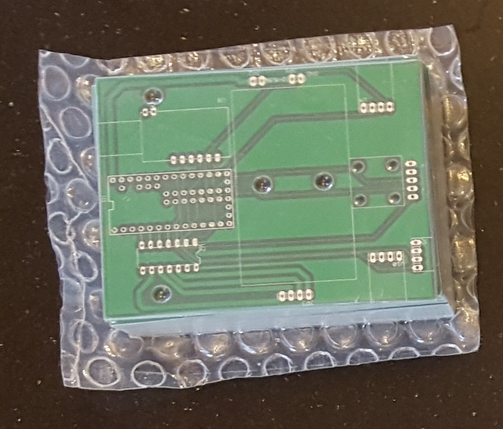
Note: The boards pictured have a smaller hole pattern for a ball caster. I redesigned the package for this article to fit a larger ball caster.
Conclusion
In this article I showed the process of taking a schematic and creating a PCB that can be ordered from online manufacturers. Boards are so cheap to make these days that unless a project is very simple, it makes sense to order the PCB. Your project will be much cleaner and take less time to wire together! In the next article I'll put the robot together and verify the electrical connections!
Downloads
Download the PCB file, Gerbers and Eagle library for the components below.
Next Article in Series: How to Build a Robot - Testing Hardware
Related Content