 Facebook
 Google
 GitHub
 Linkedin
Building an Infrared Tracker with a PICAXE 14M2 and a Stepper Motor
Tracking an infrared light source is not as difficult as you might think; a 14-pin PICAXE, a stepper motor with a driver IC, three phototransistors, and a few other components will do the trick.
This article illustrates how to build an infrared sensor that uses a stepper motor to track a light source.
A Simple Concept
Suppose you wanted to follow an object in a single plane with a pointer or some other device… and do it automatically. Not only is it possible, it's fairly easy if you break it down into separate tasks:
- Attach an infrared light source to the object to be tracked.
- Connect a stepper motor to outputs on a PICAXE microcontroller.
- Connect three phototransistors to inputs on the PICAXE microcontroller.
- Attach the phototransistor array and the pointer to the stepper motor shaft.
- Write code for the PICAXE µC to make the stepper motor turn as directed by the phototransistors.
Okay, maybe it takes a little more—such as electronic design, mechanical design, component selection, and programming skills—but this article will provide you with that work already completed. Read on!
PICAXE Newbie?
All About Circuits has a wealth of information available on the PICAXE family of microcontrollers. Best of all, the articles start at the beginning with the fundamentals. If you have experience with other µCs, PICAXEs will be a breeze for you. If you are just getting starting with micros, there's no better place to start than right here.
Infrared Light Source
Creating the infrared light source is really easy; you need an infrared LED (such as an LTE-5228A), a low voltage DC power source (think batteries), a current limiting resistor to avoid burning out the LED, and wires to connect everything together. An example is shown in the photo below.

Note that the positive voltage (red wire) is connected through the resistor to the anode of the LED and the negative lead is connected to the cathode. The resistor may be in the positive lead, as shown, or in the negative lead; either way works just as well.
You may design your infrared light source using different components and values. The one critical value is the wavelength of the light; it should be very close to 935nm because that is the wavelength at which the sensitivity of the OP505A phototransistor peaks.
Stepper Motor
A quick online search will bring up tons of information about stepper motors—more than you want or need to know. In fact, chapter 13 of the AAC electronic textbook has a page devoted to the topic.
There is no need to repeat a lot of that information here. Suffice it to say that a stepper motor is typically a low-voltage DC motor that contains magnets and coils arranged so that applying drive current to the windings in a proper order will cause the output shaft to rotate in steps. Depending upon the stepper motor design, the steps may be large or small; large steps result in more "jerky" movement while smaller steps result in smoother movement. The speed of rotation can be controlled by the speed at which the drive current is moved from winding to winding.
Stepper motors are available with two or more phases; two-phase steppers can be driven in either a unipolar configuration or a bipolar configuration. The motor chosen here is a unipolar motor. This project uses unipolar drive circuitry, but just for the record, a motor that allows for unipolar drive can also be controlled by a bipolar drive circuit.
Some stepper motors have internal gearing. These gears usually are arranged to slow the rotation and increase the torque. The motor used in this project is a small geared stepper motor and is shown in the photo below.

As you see, there is a PCB included with the stepper motor. The circuitry on the PCB includes a ULN2003A integrated circuit which contains seven Darlington transistor pairs, four of which are used. Each pair consists of two NPN bipolar junction transistors which serve as an interface between a low-current signal such as the output from a microcontroller and a higher-current load such as a winding in a stepper motor. There is a discussion of Darlington pairs in chapter 4 of the AAC electronics textbook.
The 28BYJ-48 motor, like many stepper motors, has four windings, each of which may be energized separately. Thus, it makes sense that the control PCB uses four inputs (In1, In2, In3, and In4) to the ULN2003a, each of which is connected through a Darlington driver to one of the four windings of the stepper motor. Note that there are five wires from the control PCB to the stepper motor, one for power and four for signal leads to the four windings. One LED and its current-limiting resistor are provided to indicate when power is provided to each winding.
The schematic diagram for the control board is shown below and the notes provide additional information about the operation of the circuit.

Click to enlarge
Schematic and Completed Assembly
The schematic drawing for the remainder of this project is shown below. In order to see the entire circuit, you must use this schematic and the schematic of the stepper motor controller shown in the previous section of this article.
![]()
Click to enlarge
Here's the pinout diagram for the PICAXE 14M2. Note that only two of the C port pins have ADC (analog-to-digital conversion) capabilites: C.0 and C.4. But each of the three phototransistors must be connected to an ADC pin; fortunately, there's an available ADC pin in the B port: B.5.

The entire prototype assembly for this project is shown below. Each part is labeled to coincide with the designations on the schematic diagram. Before starting construction, it's a good idea to compare each part in the schematic with the corresponding component in the photograph.
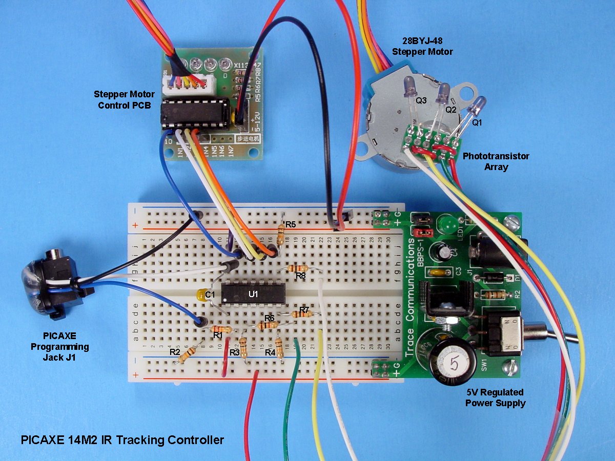
Click to enlarge
Note that the phototransistor array of three IR sensors (Q1, Q2, and Q3) is shown in the schematic drawing inside the red rectangle. In the photo of the complete assembly above, the three phototransistors are shown attached to a small piece of perfboard, which is hot-glued to the output shaft of the stepper motor.
Additional detail of that assembly is shown in the following photo. The phototransistor array should be mounted level and parallel to the flat top of the stepper motor. However, the three phototransistors should be arranged pointing in slightly different directions; 25-degree angles between the phototransistors should be perfect.
![]()
Parts List
You will need the parts in the following list. In addition, assorted wire, solder, perfboard, a well-regulated 5VDC, 500mA power supply, and a PICAXE programming cable are required.
| Part Ref. | Description | Source | Item No. |
|---|---|---|---|
| N/A | Diode, Light Emitting, 940nm, T1¾ (Qty. 1) | Digi-Key | 160-1062-ND |
| N/A | Battery, Alkaline, AAA (Qty. 3) | N/A | N/A |
| N/A | Holder, Battery, 3x AAA | N/A | N/A |
| R1 | Resistor, ¼ W, 22kΩ | Digi-Key | 22KQBK-ND |
| R2-R5 | Resistor, ¼ W, 10kΩ | Digi-Key | 10KQBK-ND |
| R6-R8 | Resistor, ¼ W, 1kΩ | Digi-Key | 1.0KQBK-ND |
| Q1-Q3 | Phototransistor, IR, NPN, 935nm, T1 | Digi-Key | 365-1066-ND |
| C1 | Capacitor, Ceramic, .1µF, 50V | Digi-Key | 399-9797-ND |
| J1 | Jack, 3.5mm, 3-Conductor | Digi-Key | CP1-3533-ND |
| U1 | Microcontroller, PICAXE 14M2+ | PHAnderson.com | PICAXE 14M2+ |
| N/A | Breadboard, Solderless, 400 Contacts | Digi-Key | 377-2094-ND |
| N/A | Motor, Stepper, 5VDC, Geared, with Control PCB | Online | 28BYJ-48 |
Code
The code for this project is reproduced below and is well commented. In addition, the BASIC commands used should be familiar to most everyone who has some experience with PICAXE microcontrollers. If you have questions, consult Manual 2 which contains explanations of all PICAXE BASIC commands.

In general, here is the flow of the code:
In lines 24 through 29, the voltage of each of the three phototransistors in the array is read to determine the amount of IR light striking them. The analog values are converted to digital values and stored in the corresponding registers.
In lines 30 through 37, the values are compared and, if the center phototransistor is getting the most IR light, nothing further happens. However, if either the right or left phototransistor is getting more light than the center, the program flow is sent to the appropriate line to turn the stepper motor either left to right (line 38) or right to left (line 49.) The process is continually repeated, thus causing the center phototransistor to always be positioned to point toward the IR light source.
The stepping pattern used is called "Full Step", which energizes two windings at a time, thus providing maximum torque from the stepper motor. Other choices include "Wave Stepping" and "Half Stepping".
Stepping speed can be controlled by changing the step delay value in line 11. Increasing the value slows the stepping speed; a value of 1000 slows the process sufficiently that the motor movement is barely perceptible. The minimum step delay value that is usable is 1, which produces maximum rotational speed; a value of 0 will stop the motor from turning and is not to be used.
Download the code using the button below.
PA14M2_IR_Tracking_Controller.zip
Demonstration Video
The video below shows the completed project in operation, albeit with the IR LED quite close to the phototransistors. The operating range really is better than it looks here; the photography lights interfered with the operation.
Note that the four LEDs on the stepper control PCB are lighting correctly to indicate which windings are energized, but you will have to slow the operation down considerably to see the pattern.
What's next?
Experimentation will reveal the useful range for tracking. Indoors, you should get about ten feet using just one LED as shown in the video. For greater range and/or outdoor use, you can add more LEDs (and current-limiting resistors) as your IR light source. Just remember that more LEDs will drain your batteries faster.
There is an obvious practical use for this circuit but, for now, you will have to think of it for yourself. In the meanwhile, study the dirsB and pinsB commands in the code to be sure you understand exactly what they do. Once you have that mastered, look into "half stepping" the motor to decrease the size of each step and provide increased positional resolution (at the cost of decreased torque).
Share your results and ideas in the comments.
Have fun!
Give this project a try for yourself! Get the BOM.
Related Content


How would you connect this project to a picaxe28x2 instead of the 14m2?