Facebook
 Google
 GitHub
 Linkedin
Building Raspberry Pi Controllers: Interactive Graphics Controllers
In part 7 of the "Building Raspberry Pi Controllers" series, readers will learn how to make an interactive graphics bouncing ball using a Raspberry Pi and physical computing techniques.
The Raspberry Pi is a versatile SBC (Single Board Computer) that allows a variety of embedded controllers to be built. The projects discussed in this hands-on series are a small example of the electronic devices and gadgets that can be built with a Raspberry Pi.
In part 7 of the Building Raspberry Pi controller series, you will learn how to make an interactive graphics bouncing ball using a few off-the-shelf electrical-electronic components and physical computing.
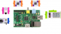
Figure 1 shows the basic component blocks required to build this interactive graphics controller.

Figure 1. The electrical-electronics and embedded hardware required to build the RPi (Raspberry Pi) interactive graphics controller.
The parts list shows the various components required to build the controller.
Project Parts List
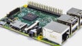
- Raspberry Pi (Model A+, B, B+, Pi2, Pi Zero, or the Pi3)
- 1 Kilo-ohm resistor (brown, black, brown, gold) 1/4W, 5%
- 10 Kilo-ohm resistor (brown, black, orange, gold) 1/4W, 5%
- photocell
- HDMI cable
- HDMI monitor or equivalent
- tactile pushbutton switch
- T-Cobbler Plus or equivalent
- solderless breadboard
- jumper wires
- jumper wires (female to male)
Pygame and the Raspberry Pi
One of the key elements behind the interactive graphics controller is the Python Pygame library. The Python Pygame library makes adding graphics to Raspberry Pi animation applications easy. The Pygame library allows games and interactive objects to be created without the hassle of developing special Python code or algorithms.
The interactive graphics controller you will build uses the Pygame library to add the bouncing ball image to a window called a canvas. Figure 2 shows the canvas built using Pygame for the bouncing ball image.

Figure 2. The bouncing ball canvas example built using the Pygame library.
The canvas dimensions are built using the Pygame instruction called size. The size instruction defines the width and height of the canvas as shown next.
size = width, height = 500, 500
In summary, the Pygame library provides the following programming enhancements to Python:
- Graphics created will not flicker.
- The graphics can be controlled with the appropriate motion speeds using the Raspberry Pi.
- The graphics can be controlled using a keyboard, mouse, or external sensors.
In addition to adding graphics, as shown in the block diagram of Figure 1, a digital sensor will control the image of the interactive controller using the Pygame library. You will build the digital sensor using a tactile pushbutton switch or a photocell to move the beachball on the canvas.
Now, let's discuss the functional interaction between the bouncing ball and the digital sensor using physical computing.
Physical Computing and the Raspberry Pi
The second element to the interactive graphics controller operation is the ability to react to physical motion. The physical interaction for our project will be a hand motioning a ball dribble as shown in Figure 3. This technique of the sensor responding to its environment using code and electronics is called physical computing.

Figure 3. The physical computing environment for the sensor (photocell) with a supporting electronic circuit wired on a solderless breadboard. The motion of the hand simulates a ball dribble.
The environment for the sensor is the solderless breadboard and supporting pulldown resistor circuit. As the hand passes over the sensor, an electrical signal is generated. This electrical signal is then processed by the Raspberry Pi by way of the Python code embedded inside of the microcontroller's memory. The Pygame library will create a bouncing ball canvas allowing the graphics to move according to the Python code motion parameters. The motion parameters for this interactive animation is a diagonal direction up-down movement of the beachball on the canvas.
You will use a photocell cell as the hand motion sensor along with the Python code and Pygame library to build your physical computing-based interactive graphics controller. With an understanding of physical computing and the Pygame library, you are now ready to build the interactive graphics controller.
Electronics Circuit Wiring Methods
To build the electronic photocell sensor circuit, you will use a solderless breadboard and jumper wires. As shown in Figure 3, the electronic photocell sensor circuit's output will be wired to a Raspberry Pi's GPIO (General Purpose Input Output) pin. You will wire the circuit's output directly to GPIO pin 25 of the Raspberry Pi.
Before building the controller, a tactile pushbutton switch test circuit will be used to check the electrical circuit interface of the digital switch. The pulldown resistor of 1Kilo-ohms will provide the digital voltage signals of 0V and 3.3VDC to the Raspberry Pi's GPIO pin 25 when the tactile pushbutton switch is released and pressed. Figure 4 shows the tactile pushbutton switch test circuit wiring diagram.

Figure 4. Tactile pushbutton switch test circuit wiring diagram.
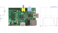
The 40 pin male connector unfortunately doesn't have the GPIO pins identified on the PCB (Printed Circuit Board). To help wire the tactile pushbutton switch circuit, Figure 5 provides a wiring reference for the Raspberry Pi's GPIO connector pinout.

Figure 5. Raspberry Pi GPIO connector pinout.
Another method of wiring the electronic photocell sensor circuit to the Raspberry Pi is to use the Adafruit T-Cobbler Plus as shown in Figure 6. The T-Cobbler Plus is an electrical breakout board providing access to the Raspberry Pi's GPIO pins.

Figure 6. The Adafruit T-Cobbler Plus.
The T-Cobbler Plus inserts into a standard solderless breadboard and jumper wires are attached to the desired GPIO pins. A flat ribbon cable attaches between the T-Cobbler Plus and Raspberry Pi's electrical connectors. Figure 7 show the tactile pushbutton switch circuit wired to the T-Cobbler Plus mounted on a solderless breadboard. The T-Cobbler Plus is attached to a Raspberry Pi2 using a flat ribbon cable.

Figure 7. The author's interactive graphics controller's tactile pushbutton switch test circuit.
With the test circuit wired on the solderless breadboard, you are now ready to check the interactive graphics controller's operation using the Python code shown in Listing 1.
Listing 1. ButtonBouncingBall.py

#Include Python Libraries
import sys, pygame
import time
import RPi.GPIO as io
io.setmode(io.BCM)

#Make pin assignment
button_pin = 25

#setup button_pin as an input
io.setup(button_pin, io.IN)


pygame.init( )

#Set canvas parameters
size = width, height = 500, 500
speed = [100, 100]
white = 255,255,255

#Display title on canvas
pygame.display.set_caption("Bouncing Ball")

screen = pygame.display.set_mode(size)
ball = pygame.image.load("beachball2.png")
ballrect = ball.get_rect()

while 1:
    for event in pygame.event.get():
        if event.type == pygame.QUIT: sys.exit()
    if io.input(button_pin):#If button is pressed, move beachball
       ballrect = ballrect.move(speed)
    if ballrect.left < 0 or ballrect.right > width: #Move beachball up
        speed[0] = -speed[0]
    if ballrect.top < 0 or ballrect.bottom > height: #Move beachball down
        speed[1] = -speed[1]

    screen.fill(white)#Set background of canvas
    screen.blit(ball, ballrect)
    pygame.display.flip()
    time.sleep(0.1)#Wait for 100ms before next button press
ButtonBouncingBall_materials.zip
Testing the Interactive Graphics Controller
Before the interactive graphics controller can be tested, you'll need to unzip the ButtonBouncingBall_materials folder within your Raspberry Pi file directory. You'll see the beachball2.png and the ButtonBouncingBall.py files in the zipped folder.
Next, run the application by opening the LXTerminal located on the Raspberry Pi's desktop. Type the Linux command "cd" (change directory) into the LXTerminal to gain access to the ButtonBouncingBall.py Python code. The key functions of the Python code are highlighted by comment statements. Review these comment statements to understand how the Python code works before running it.
The Linux command ~sudo python ButtonBouncingBall.py will be typed into the LXTerminal editor as shown in Figure 8 to run the application.

Figure 8. The ButtonBouncingBall.py Python application being executed in LXTerminal.
Once the code has been executed, the Bouncing Ball canvas will be displayed on the HDMI monitor screen as shown in Figure 9.
Figure 9. The ButtonBouncingBall.py code running on the Pygame canvas.
Press the tactile pushbutton switch with your finger several times to see the beachball bounce diagonally down the canvas. Congratulations on building your interactive graphics controller! The final project build is to add a hand-dribble detection feature as discussed, using an electronic photocell sensor circuit.
Hand-Dribble Detection Feature
To bounce the beachball by hand-dribble requires the tactile pushbutton switch to be replaced with an electronic photocell sensor circuit. The electronic photocell sensor circuit is wired as a digital switch. Placing your hand over the photocell will provide a binary 1 (3.3V) control signal to be read by the Raspberry Pi. The Raspberry Pi will process this digital control signal and allow the beachball to move or bounce.
Removing your hand from the photocell provides a binary 0 (0V) digital control signal. The beachball stops bouncing as controlled by the Raspberry Pi. The wiring diagram for the hand-dribble detection circuit is shown in Figure 10.

Figure 10. The hand-dribble detection circuit wiring diagram.
I've included another picture of the final interactive graphics controller project build with the hand-dribble detection feature shown in Figure 11 as a reference.

Figure 11 The author's final project build of the interactive graphics controller. Note the photocell replacing the tactile pushbutton switch for hand-dribble detection.
You can review the operation of the project shown in the small video clip located below. Run the Python application code using the Linux command discussed earlier. As you provide a hand-dribbling motion to the electronic photocell sensor, the beachball will bounce on the Pygame canvas.
Again, congratulations on successfully adding the hand-dribble detection feature to your interactive graphics controller. Next time, we'll explore adding a camera to the Raspberry Pi for photo imaging fun.
Give this project a try for yourself! Get the BOM.