 Facebook
 Google
 GitHub
 Linkedin
Building Raspberry Pi Controllers: IR Remote Event Counter
In part 4 of this Build Raspberry Pi Controllers series, the reader will learn how to build an IR Remote Event counter using littleBits.
Previous Articles in the Raspberry Pi Controllers Series
Build a Raspberry Pi Pushbutton Switch
Build an Object Detection DC Motor Controller
Intro
I've been exploring the electrical abilities of littleBits modules for a year and they are great for quickly building electronic gadgets and devices. I've used these awesome electronic modules in several Career and Technical Education (CTE) courses I teach at local Alabama technology high schools and a community college. I also provided several littleBits projects in my recent Arduino Electronics Blueprints book published by Packt Publishing. In this book, the littleBits projects illustrated basic circuit interfacing techniques for buidling awesome Arduino devices.
The library of littleBits modules allows a variety of electronic devices to be built easily: no soldering of electronic components onto perfboards or PCBs is required. The two major requirements in using littleBits are the willingness to have fun and be creative. In this continuing Building Raspberry Pi Controller series, you will learn how littleBits modules can be wired to a RPi by building a simple IR remote activated event counter. The block diagram for our IR remote event counter is shown in Figure 1. The littleBits modules and electronic components required to build the counter are shown in the Project Parts List.

Figure 1. The electrical-electronics and embedded hardware required to build the IR remote event counter
Project Parts List
- Raspberry Pi (Model A+,B, B+, or the Pi 2)
- (Q1) 2N2222 NPN transistor or equivalent
- CNY74-4H-ND opto-isolator IC [16 pin DIP package]
- (R1) 220 ohm resistor (red, red, brown, gold), 1/4W, 5%
- (R2) 470Kilo-ohm resistor (yellow, violet, yellow) 1/4W, 5%
- (R3) 1Megohm resistor (brown black, green), 1/4W, 5%
- Raspberry Pi Cobbler or equivalent
- littleBits power bit
- littleBits remote trigger
- littleBits proto module x 2
- littleBits mounting board
- solderless breadboard
- jumper wires (hand stripped 22 AWG [American Wire Gauge]) solid wires or Adafruit Breadboard wires Product ID: 153)
- (VCC1) 6VDC Battery pack
- 9V Battery and cable or equivalent
littleBits Modules
To make the IR remote event counter you will use the littleBits modules. The littleBits are colorful electronic modules that provide specific electrical functions for devices and gadgets. By connecting the modules in unique and creative ways, interesting innovative electronic devices and gadgets can be built. The Raspberry Pi will allow various littleBits module's electrical function information to be displayed on a monitor using simple wiring connections and the Python programming language.

Figure 2. littleBits modules come in a variety of electrical devices and functions
There are three metal pins that allow the littleBits electronics modules to work. They consist of the following signal names:
- vcc (+5V power signal)
- sig (electrical signal)
- gnd (electrical ground)
The littleBits electronic modules include plastic bitSnaps that have three metal pins for providing the electrical connections. The bitSnap electrical connections are shown in the following figure.

Figure 3. The heart of the BitSnap is the electrical connections of vcc, sig, and ground.
To reduce errors in building a gadget or device, small magnets are placed inside of the littleBits bitSnaps. The electronic modules will connect to each other when properly attached. Incorrect electronic module connections will repel each other. The littleBits modules provided in the Project Parts List of this article will be used to build the IR remote event counter. As a reference here are the littleBits modules you will use for the project.

Figure 4. The littleBts modules for the IR remote event counter.
The TSOP382 IR Sensor
The littleBits remote trigger is an electronic sensor able to detect infrared (IR) signals. To rapidly build the event counter a littleBits electronic module will be used. The remote trigger module has an IR sensor (TS0P382) and a pre-amplifier circuit soldered onto a small printed circuit board (pcb). The TSOP382 sensor is an IR receiver circuit packaged inside a small three lead epoxy component package. When detecting an IR signal, the TSOP382 sensor will generate a series of binary pulses.
In addition to the TSOP382 IR sensor, the litleBits remote trigger module consists of several amplifiers (operational amplifiers) and transistors. The remote trigger operational-amplfiers are used for IR signal low level signal conditioning and output buffering of the internal produced digital pulses. The transistors provide small gain amplification and output switching for the remote trigger module.The complete circuit schematic diagram of the remote trigger module can be found at the littleBits website.
Wiring the Remote Trigger Module
With an understanding of littleBits modules , the remote trigger, and the TSOP382 IR sensor, you are ready to begin building the RPi project. In the next figure, you will see a wiring diagram showing how to attach the littleBits remote trigger to the RPi. Using the materials provided in the Project Parts List, build the remote trigger - RPi interface circuit. As an additonal reference, I included a circuit schematic diagram of the interface circuit for the intermediate to advanced electronics maker.

Figure 5. The remote trigger interface wiring diagram.

Figure 6. The remote trigger interface circuit schematic diagram.
The trick behind attaching the remote trigger module to the RPi is to use a littleBits proto module. The proto module is a special wiring board that allows electrical, electronic components, and circuits to be wired to the littleBits modules. A closer view of the proto module is below.

Figure 7. The littleBits proto-module
The proto module will be used to operate the littleBits number module by taking the binary data of the RPi to increment the value on the two digit seven segment LED display. Before moving on to the testing stage of the remote trigger, check for wiring errors. If you have no wiring errors, lets load a Python test code for checking the remote trigger interface to the RPi.
Testing the Remote Trigger Circuit
You have built your remote trigger interface circuit and are now ready to test it. A small Python test code is required to insure the circuit is working correctly. The test code is shown below. The Python test code can be typed onto the LXTerminal by opening the nano editor with the linux command ~sudo nano remotetrigger.py. Also, the Python code can be saved on your RPi's SD card by clicking the code button below.
With the remote trigger Python test code entered into the LX Terminal, type the Linux command ~sudo python remotetrigger.py after the prompt onto the screen. Attach the 9V battery and cable to the littleBits power module. Apply power to the circuit by sliding the power switch to the on position. The onboard power LED indicator will be turned on. Next, take an ordinary IR handheld remote and point it at the littleBits remote trigger. Press any button on the IR handheld remote and notice the Python test code displaying the button counts on the monitor as shown in Figure 8. Congratulations on building your remote trigger interface circuit! Turn off the power from the remote trigger interface circuit.
####################################
#      Remote Trigger Test Code    #
#      Jan 1/15/16                 #
#      by Don Wilcher              #
####################################


import RPi.GPIO as GPIO
import time

GPIO.setmode(GPIO.BCM)

button = 4

GPIO.setup(button, GPIO.IN)

count = 0

while True:
    inputValue = GPIO.input(button)
    if (inputValue == True):
        count = count +1
        print("Button pressed " +str(count) + " times:")
        time.sleep(.3)
       # time.sleep(.01)

#Listing 1. Remote Trigger Python Test Code

Figure 8. A properly working remote trigger interface circuit.
Final Hardware Build
You successfully built the remote trigger interface circuit and it's ready for the final hardware build of the the project. As discussed previously, a second proto module will be used to wire the littleBits number module to the RPi. In order for the wiring connection to occur, a transistor circuit is needed. In the previous Building RPi Controllers project, I discussed the transistor switch and how it operates a small DC motor. The same electrical wiring technique used in the object detection DC motor controller project will be used to operate the littleBits number module. With the remaining components left from the Project Parts List, build the transistor-littleBits number driver circuit using the wiring diagram shown next.

Figure 9. The complete IR remote Event Counter wiring diagram. Note: The transistor-littleBits number driver circuit is shown in at the right section of the breadboard.
Again, I included a circuit schematic diagram of the driver circuit as an additional reference for the intermediate to advanced electronics maker.
![]()
Figure 10. The littleBits-transistor number driver circuit
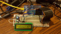
Before adding the final Python code to the RPi, check the transistor driver circuit wiring carefully. With no wiring errors found, you have completed the final build of the IR Event Counter. To provide a rigid circuit platform for the littleBits modules, you can place them on the mounting board. I provided a picture of my assembled IR remote event counter using the littleBits mounting board. The only activity remaining is installing and running the IR Remote Event Counter Python code.

Figure 11. The assembled IR Remote Event Counter. The mounting board provides a rigid platform for the littleBits modules.
The IR Remote Event Counter
The final step to completing this cool RPi controller project is to install and run the Python code. The Python code shown below is a program re-use from the pushbutton project. The variable names were changed to reflect the physical components wired to the RPi. The code works by pressing any button on an ordinary IR remote to increment the value on the littleBits number module. With every button pressed on the remote, the number display will increment its value by one.
The entire Python program can be typed onto the LXTerminal by opening the nano editor with the linux command ~sudo nano IREventCounter.py. Also, the python program can be saved on your RPi's SD card by clicking the code button below. With the IR event counter Python code entered into the LX Terminal, type the Linux command ~sudo python IREventCounter.py after the prompt onto the screen. Take an IR handheld remote and point it at the remote trigger. Press any button on the handheld remote and the littleBits number module will begin to increment. Congratulations on building another RPI Controller successfully! You now have a functioning event counter to experiment with. The RPi also prints the state of the counter on a monitor's screen with each button press as well. Figure 12 shows the RPi printing the state of the littleBits number counter. I've provided a small video clip showing the IR remote event counter in action.

Figure 12. The RPi prints the state of the IR Event Counter on a monitor's screen.
Explore the operation of the littleBits number module by moving the slide switch to the various function positions on the board. As always, record your observations in a lab notebook. An application that comes to mind for the IR Remote Event Counter is keeping score for a game or sporting event, but you can explore other applications of your own using this awesome electronic counter. Next time, we'll investigate how to read analog data with an RPi.
###################################
#       IR Remote Event Counter   #
#        Jan 1/15/16              #
#        by Don Wilcher           #
###################################

# installing Python Libraries
import time
import RPi.GPIO as GPIO

# defining RPi I/O pins
GPIO.setmode(GPIO.BCM)
number = 18
button = 4

# setup for LED and button definitions as I/O pins
GPIO.setup(number, GPIO.OUT)
GPIO.setup(button, GPIO.IN)

# Continuous loop
while True:
    inputValue = GPIO.input(button)  #assigning button value to inputValue variable
    if (inputValue== True):          #Conditional test of inputValue variable
      GPIO.output(number, GPIO.HIGH) #if inputValue variable is true, increment littleBits number by 1
      print("COUNTER_TRIGGERED")     # print state of Counter
      time.sleep(0.5)                # wait 500ms
      GPIO.output(number, GPIO.LOW)  # if inputValue variable is false, don't increment littleBits number
      print("COUNTER_NOT_TRIGGERED")# print state of Counter

#Listing 2. The IR Remote Event Counter Python Code
Next Article in Series: Building Raspberry Pi Controllers Part 5: Reading Analog Data with an RPi
Give this project a try for yourself! Get the BOM.


Whilst I don’t mind very simple programming examples the writer could have added a note about the use of interrupts for this type of application.
Too often I see programs that started as simple examples which have organically grown into a large poor running code.