Facebook
 Google
 GitHub
 Linkedin
Building Raspberry Pi Controllers Part 6: Displaying Messages on a LCD with a RPi
Readers will learn how to wire a standard 16x2 LCD (liquid crystal display) to a Raspberry Pi to display messages.
This project is a continuation of the Build Raspberry Pi Controller series.
Previous Articles:
Build a Raspberry Pi Pushbutton Switch
Build Raspberry Pi Controllers: LED Flasher
Build an Object Detection DC Motor Controller
Building Raspberry Pi Controllers: IR Remote Event Counter
Reading Analog Data with an RPi
LEDs are used as direct replacements for incandescent light bulbs because of advantages like less heat dissipation and long life expectancy. Besides being a light source, LEDs are flexible enough to be used in marquees for displaying messages. Letters and numbers can easily be created using seven segment LED displays using a simple wiring scheme obtained from the optoelectronic component's datasheet. To create multi-letter messages using alphanumeric characters (letter - number combinations), a technique of operating each seven segment LED digit with an electronic driver circuit is needed. This technique of operating each seven segment LED digit with an electronic driver circuit is called multiplexing. Although seven segment LED displays are energy efficient and easy to use, a major problem for the optoelectronic component in sunlight is washout.
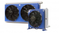
The liquid crystal display (LCD) was developed to remove heat and washout. Also, LCDs allow a variety of characters and complex graphics to be created as well. In this project, you will investigate the LCD using the Raspberry Pi. The Raspberry Pi will allow simple text messages to be displayed on an LCD using the Python programming language. You will use the Adafruit LCD library to experiment with the RPi LCD controller to display simple text messages. The block diagram for our RPi LCD controller is shown in Figure 1. Also, I included the Parts List for building the RPi LCD controller as well.

Figure 1.The electrical-electronics and embedded hardware required to build the RPi LCD controller.
Project Parts List
- Raspberry Pi ( Model A+, B, B+, or the Pi 2)
- (R1) 10Kilohm or 100Kilohm trimmer potentiometer
- LCD 16x 2 Character display
- Raspberry Pi Cobbler
- solderless breadboard
- photocell
- 10Kilohm resistor (brown, black, orange, gold)
- jumper wires (hand stripped 22 AWG[American Wire Gauge]) solid wires or Adafruit Breadboarding wires
LCD Basics
Before we begin our hands-on investigation of LCDs, let's find out how they work. The LCD is traditionally used to show data, graphics, or both on electrified glass plates. Typical LCD parts consist of a controller and a glass substrate material. LCD segments mounted on the glass substrate material are operated by an electronic controller that consists of a microprocessor or microcontroller.
A typical block diagram of an LCD with its controller is shown in Figure 2.

Figure 2. Block diagram for a typical LCD.
The LCD's crystal segments are placed between glass plates with electrodes. In order for the crystal segments to form letters or characters, a small AC RMS voltage is needed. The AC RMS voltage turns on the crystal segments.The electronic device responsible for managing this electrified voltage for the crystal segments is the LCD controller. To assure the timing sequences to turn on or off the crystal segments are correct, a microprocessor or microcontroller is used inside of the LCD controller. Typical LCD controllers used to operate the crystal segments are the HD44780 and KS0066 devices. LCDs come a variety of column-row versions such as 8x1,16x1, 20x 2, and 20 x4. The display unit you will be using for this project is the standard 16 x 2 LCD. A typical LCD and its controller, identified by U2, are shown in the figure below.

Figure 3. The backside of a typical LCD. The LCD controller is referenced by the "U2" designator shown on the PCB (Printed Circuit Board).
Now that we have basic knowledge of the LCD, you are ready to begin building the RPi LCD controller.
Tech Notes:
- RMS is the abbreviation for Root Mean Square which is a continuously concentric varying signal. RMS is usually associated with AC voltage and current in electrical circuits.
- Additional information on LCDs and OLEDs (Organic Light Emitting Diodes) can be found in the book Arduino Electronics Blueprints.
Building a RPi LCD Controller
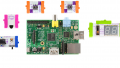
Like the previous RPi projects in this series, you will build the LCD controller using a few electrical-electronic components. The solderless breadboard is an indispensable prototyping tool for building electronic projects and will be used to wire the LCD to the RPi. Also, you will wire a potentiometer (either a 10Kilohm or 100Kilohm) to the LCD to adjust the display's contrast as well. I provided a basic wiring diagram shown in Figure 4 to aid in building the LCD controller. I also included two circuit schematic diagrams as additional reference designs for the intermediate to advanced electronics maker.
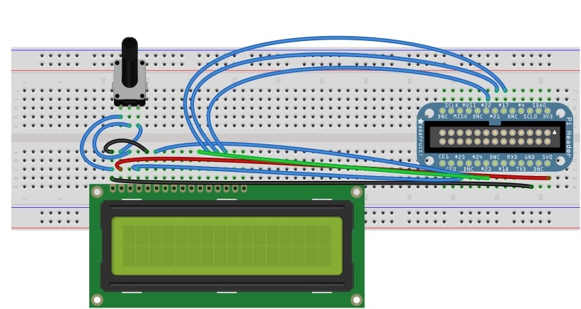
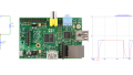
Figure 4. The LCD Controller wiring diagram.
The equivalent Fritzing circuit schematic diagram for the LCD Controller is shown next.

Figure 5. The LCD Controller circuit schematic diagram.
If the Fritzing circuit schematic diagram is a little challenging to read, here's my circuit schematic diagram for the LCD Controller.
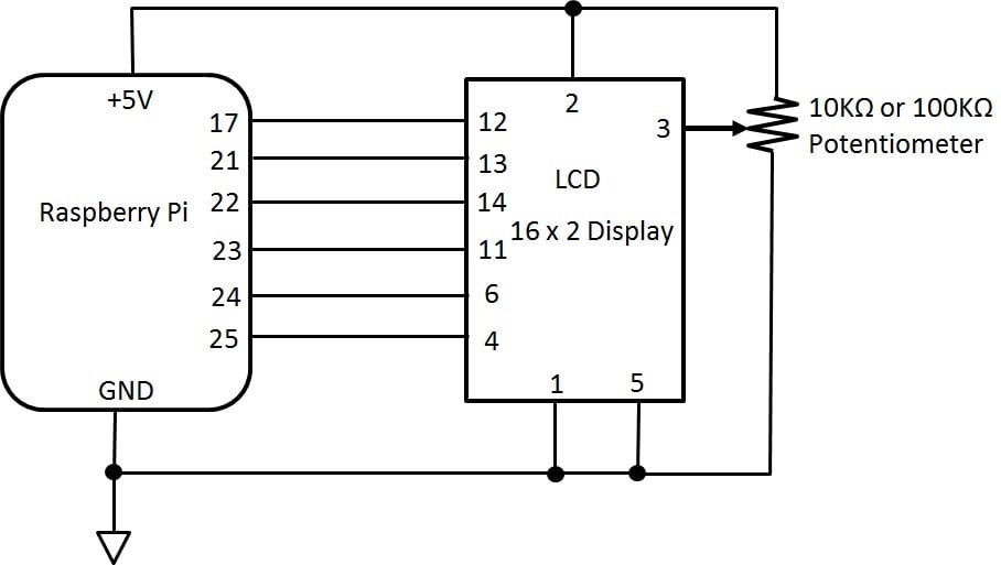
Figure 6. The author's circuit schematic diagram for the RPi LCD controller.
Before moving on to testing the RPi LCD controller, check for wiring errors. If you have no wiring errors, you are ready to test the LCD contrast control before loading the Adafruit LCD Python code to the RPi.
Tech Note:
Fritzing is an open-source hardware initiative that makes electronics accessible as a creative material for anyone. Source:http://fritzing.org/home/
Testing the RPi LCD Controller's Electrical Wiring
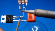
With the RPi LCD controller completely wired on the solderless breadboard, you are now ready to electrical test the device. To test the LCD controller's electrical wiring is basically to power up the RPi and adjust the display's contrast using the potentiometer. You may see a series of square blocks, this depends on the potentiometer's setting. I've included a picture of my LCD controller as a reference shown in Figure 7. If not, adjust the contrast control to display the square blocks on the LCD. Congratulations, you have successfully wired your LCD to a RPi! The final stage of this project is to add the Adafruit LCD python code to the RPi to display a message.

Figure 7. The author's working LCD controller.
Adding the Adafruit LCD Python Code
You are one step away to having a fully functional LCD controller. All that remains is to add the Adafruit LCD Python code to the RPi to display messages on it. The LCD python code is part of the Adafruit Raspberry Pi example software bundle. The HD44780 is an electronic controller typically used with LCDs. Therefore, the example bundle will include a software library to operate the LCD controller properly. The software bundle can be obtained from Github. Note, the Adafruit LCD python code is not a usual library like most RPi software bundles. Therefore, you must download the software files in a specific order. To obtain the files in the correct order, you may open the LXTerminal and type the Linux command ~sudo apt-get install git. You may now download the files from Github using the following Linux command:
$ git clone https://github.com/adafruit/Adafruit-Raspberry-Pi-Python-Code.git.
With the folders properly installed onto the RPi, you can change the code directory using the linux command:
$cd Adafruit-Raspberry-Pi-Python-code
follow by
$ cd Adafruit_CharLCD
This file structure is shown in Figure 8.

Figure 8. The file structure for the Adafruit-Raspberry-Py-Python-Code example bundle.
Before the python code can be used correctly, you will need to change the Adafruit_CharLCD.py file.To change the code open the nano editor with the Linux command ~sudo nano Adafruit_CharLCD.py. Now, the line to change is:
<strong>def</strong>_init_(self, pin_rs=25, pin_e=24, pins_db=[23, 17, 21, 22], GPIO = None):
You may replace the number 21 with 27 so the revised line of code will look like:
<strong>def</strong>_init_(self, pin_rs=25, pin_e=24, pins_db=[23, 17, 27, 22], GPIO = None):
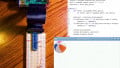
Save the change and exit from the nano editor. You can execute the python code by typing onto the LXTerminal with the Linux command:
~sudo python Adafruit_CharLCD.py
The following screenshot shows this command typed onto the LXTerminal.

Figure 9. Running the Adafruit_CharLCD.py on the RPi using the sudo Python command.
With the python code running on the RPi, the following message will be displayed on your LCD controller.

Figure 10. The Adafruit 16x2, Standard LCD message displayed on the author's controller.
Congratulations on building your LCD Controller. You now have an electronic device that can display simple messages. For reference, I've included the code for the Adafruit_LCD.py shown in Listing 1 as well as a short video clip of the LCD controller in action.

The full code can be downloaded from the link below.
Design Challenges
Now that you have a working LCD controller, let's have some fun with this awesome device by way of basic design modifications. Here are two challenges for you to explore your LCD controller further.
Displaying a new message: Edit the python code where the message "Allaboutcircuits, Standard LCD" will be shown on the LCD. The final message should be displayed as shown in Figure 11.
Adjusting the contrast with your hand: Instead of using a potentiometer to adjust the LCD contrast, replace it with a photocell circuit as shown in Figure 12. Placing your hand over the photocell should display the new message used in the first design challenge. As always, record your design changes in a lab notebook.

Figure 11. Design Challenge 1: Modify the python code to display the new message.

Figure 12. Design Challenge 2.Add a photocell circuit to control the LCD contrast.
Next time, we'll explore the world of Physical Computing by making an interactive graphics bouncing ball.
Next Article in Series: Building Raspberry Pi Controllers: Interactive Graphics Controllers
Give this project a try for yourself! Get the BOM.