 Facebook
 Google
 GitHub
 Linkedin
Building Raspberry Pi Controllers Part 5: Reading Analog Data with an RPi
Learn how to read electrical signals and data from an analog device using the Step Response technique in Part 5 of the Building Raspberry Pi Controllers series.
A continuation of the helpful Building Raspberry Pi Controllers series. Here you'll learn how to read analog data with an Raspberry Pi.
Previous Articles:
Build a Raspberry Pi Pushbutton Switch
Build Raspberry Pi Controllers: LED Flasher
Build an Object Detection DC Motor Controller
Building Raspberry Pi Controllers: IR Remote Event Counter
Intro
The RPi (Raspberry Pi) has the ability to perform a variety of electrical-electronic functions such as reading digital data from an electric pushbutton switch, controlling a DC motor, and flashing LEDs. The only electronic function it's not capable of doing is reading electrical signals and data from an analog device. Although the RPi has a multitude of GPIO pins, HDMI, an audio jack, LCD, and camera connectors, it's not capable of reading analog signals because it lacks an ADC (Analog to Digital Converter) circuit. Wiring an ADC to the RPi is quite easy to do, but there is another technique that can be used to read analog electrical signals or data: here, you'll learn how to read electrical signals from an analog device with an RPi using the Step Response technique. The electronic components and circuit required to read analog electrical signals is shown in the block diagram of Figure 1. In addition, a Parts List is provided showing all of the electronic components required to build the RPi project.

Figure 1. The electrical-electronics components, circuit, and hardware required to the build the Analog Device interface circuit
Project Parts List
- Raspberry Pi (Model A+,B, B+, or the Pi 2)
- (R1) 1Kilo-ohm resistor (brown, black, brown, gold), 1/4W, 5%
- (R2) 1Kilo-ohm resistor (brown, black, brown, gold), 1/4W, 5%
- (R3[POT1]) 10Kilo-ohm potentiometer
- (C1) 220nF capacitor or 100nf capacitor (220nf =0.2uF and 100nf=0.1uF)
- Raspberry Pi Cobbler or equivalent
- Solderless breadboard
- Jumper wires (hand stripped 22 AWG [American Wire Gauge]) solid wires (VCC1) 6VDC Battery pack
Step Response Technique: Reading Analog Data
As briefly mentioned in the introduction, the RPi isn't able to read electrical analog signals or data. The reason it's not able to read such signals or data is because the RPi's BCM (Broadcom) microcontroller doesn't have an ADC circuit embedded within its silicon substrate. Two alternative methods that can allow the RPi to read electrical analog signals are to wire an external ADC IC (the MCP3008) or use a simple charging-discharging circuit. In this project, you will be using a charging-discharging circuit to read electrical analog signals. The charging-discharging circuit will allow continuous data to be read by the RPi using a step response technique. The step response technique works by seeing how a RC (resistor-capacitor) circuit responds to an electrical pulse switching from a low to high signal transition within a specified time frame. The electrical response behavior of the RC circuit is based on the charging and discharging of the capacitor receiving an electrical pulse or step signal. Figure 2 shows an electrical circuit model of a basic RC circuit. The applied step signal and the circuit's charging-discharging response is shown in the waveform plots of Figure 3. To create the RC circuit and its step response waveforms, I used a free circuit simulation software package called Micro-Cap.

Figure 2. A basic RC circuit used in the Step Response technique. NOTE: R2 is the analog device providing the continuous signal values for the circuit.
![]()
Figure 3. The step input pulse signal [blue:V(1)(V)] and the RC circuit's charging-discharging response [V(3)(V)]
In addition, as shown in Figure 3, the step input pulse signal is applied to the RC circuit for 5ms (millisecond). The capacitor (C1) is charged during that time through resistors R1 and R2. Once the capacitor is fully charged, at the falling edge of the step pulse signal the capacitor discharges through resistor R3. The discharge time is set for 1ms. This charging and discharging of the capacitor can be accomplished using Python code implemented on an RPI. As this continuous cycle of charging and discharging occurs, a Python code software counter is used to provide an equivalent continuous value of the analog device's data being read by the RPi. The software counter's value is constantly being updated and displayed based on the main application code being cycled continuously. If you're interested in exploring the electrical behavior of this RC circuit, the Micro-Cap simulation code file can be obtained below. I've included two circuit schematic diagrams showing the charging and discharging circuits wired to the RPi. Figures 4 and 5 show the charging and discharging circuits wired to the RPi's GPIO pins 18 and 23. For additional information on RC circuits and how electrical transient responses work, check out Vol. I - Direct Current (DC), Chapter 16: RC and L/R Time Constants.
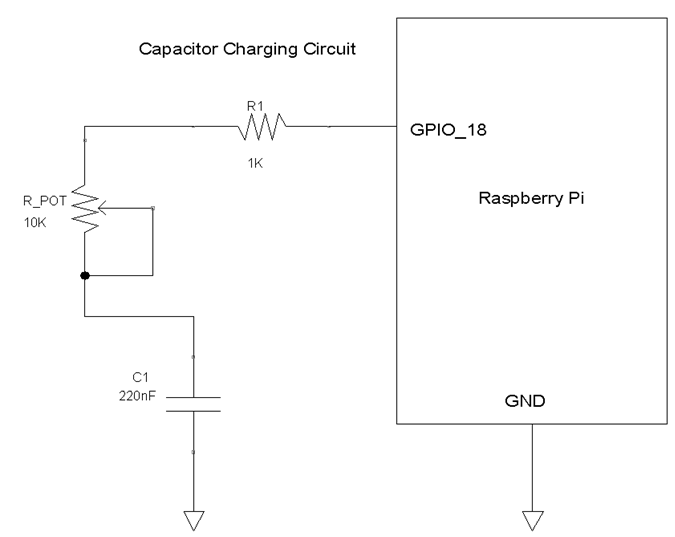
Figure 4. The RPi C1 capacitor charing circuit interface.

Figure 5. The RPi C1 capacitor discharging circuit interface.
With a basic knowledge of how to read electrical analog signals or data using the step response technique under our belts, let's build a RPi analog device interface circuit!
RPi_Capacitor_Charging_Discharging_Circuit.zip
Building an RPi Analog Device Interface Circuit
With the electronic components obtained from the Project Parts List, you are now able to wire the RPi analog device interface circuit. Following the parts placement shown in Figure 6, wire the RPi analog device interface circuit on a solderless breadboard. As an additional wiring reference, I included a circuit schematic diagram of the interface circuit for the intermediate to advanced electronics maker.

Figure 6. The analog device interface wiring diagram.
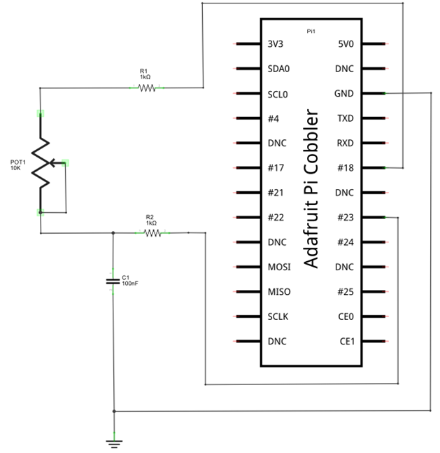
Figure 7. The analog device circuit schematic diagram.
Also, here's my assembled analog device interface circuit you can use as a reference model:

Figure 8. The assembled analog device interface circuit built on a solderless breadboard.
Before moving on to the testing stage of the analog device interface circuit, check for wiring errors. If you have no wiring errors, let's load a Python code for checking the analog device interface circuit to the RPi.
Testing the Analog Read Function and Interface Circuit
You have built your analog device interface circuit and are now ready to test it! A small Python application code is required to ensure the circuit is working correctly. The application code is shown in Listing 1. The Python application code can be typed onto the LXTerminal by opening the nano editor with the linux command ~sudo nano pot_step.py. Also, the Python code can be saved on your RPi's SD card by clicking the code button below.
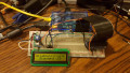
With the pot_step Python code entered into the LX Terminal, type the Linux command ~sudo python pot_step.py after the prompt onto the screen. A stream of scrolling analog data should be visible on the screen. By rotating the potentiometer, the analog values will change as shown in Figure 9. Congratulations on building your analog device interface circuit! I've included a small video clip showing the operation of this awesome analog device interface circuit for your reference. You can explore this simple unique interface circuit further by replacing the 10Kilo-ohm potentiometer with a photocell. Waving your hand over the photocell will change the detected light displaying its value on the screen. As always, record your circuit modifications in a lab notebook. Next time, you learn how to wire an LCD (liquid crystal display) to the RPi and display messages using the Python programming language.

Figure 9. The potentiometer analog values being displayed on a video monitor screen
Listing 1.

####################################
#         Analog Read Code         #
#         by Simon Monk            #
#         modified by Don Wilcher  #
#         Jan 1/31/15              #
####################################

# include RPi libraries in to Python code
import RPi.GPIO as GPIO
import time

# instantiate GPIO as an object
GPIO.setmode(GPIO.BCM)

# define GPIO pins with variables a_pin and b_pin
a_pin = 18
b_pin = 23

# create discharge function for reading capacitor data
def discharge():
    GPIO.setup(a_pin, GPIO.IN)
    GPIO.setup(b_pin, GPIO.OUT)
    GPIO.output(b_pin, False)
    time.sleep(0.005)

# create time function for capturing analog count value
def charge_time():
    GPIO.setup(b_pin, GPIO.IN)
    GPIO.setup(a_pin, GPIO.OUT)
    count = 0
    GPIO.output(a_pin, True)
    while not GPIO.input(b_pin):
        count = count +1
    return count

# create analog read function for reading charging and discharging data
def analog_read():
    discharge()
    return charge_time()

# provide a loop to display analog data count value on the screen
while True:
    print(analog_read())
    time.sleep(1)
Next Article in Series: Building Raspberry Pi Controllers Part 6: Displaying Messages on a LCD with a RPi
Give this project a try for yourself! Get the BOM.


Hi Don Wilcher, im new to circuits, python and pi, trying to test out this project for a project i have planed.
will this work if i am using a polyester capacitor 220nanoFarad, 63volts with ±10% tolerance? to read any type of potentiometer value with my pi. and is it safe?
thanx
and using 1 kilo-ohm (Brown, Black, Red, Gold) ±5% resistor is that similar as
1Kilo-ohm resistor (brown, black, brown, gold), 1/4W, 5%