Facebook
 Google
 GitHub
 Linkedin
Build Raspberry Pi Controllers: LED Flasher
In this project, you'll learn how to wire an LED and flash it using the Raspberry Pi. Also, to isolate the Raspberry Pi's + 3.3VDC compliant output pins from supply voltages greater than this power source, an opto-isolator will be introduced as well.
Flash LEDs using your RPi!
LEDs (light emitting diodes) are commonly used in consumer, medical, automotive, and industrial products. They provide visual status alerting us to the operational conditions of electronic toys, smartphones, and consumer devices. LEDs also provide stunning effects for products aided by color, intensity, and flashing rates. These electronic light sources are continually replacing the incandescent bulb as well as CFLs (compact fluorescent lights) because of their high energy efficiency, brightness, and functional longevity. In this second part series of Building Raspberry Pi Controllers, you'll learn how to connect an LED to a Raspberry Pi and control it with a tactile pushbutton switch. The electronic device you'll build using this simple LED controller is a pushbutton switch actuated electronic flasher.
Previous Articles in this Series
Build a Raspberry Pi Pushbutton Switch
Project Parts Lists
Components to build the Raspberry Pi LED flasher are listed below.
- Raspberry Pi (Model A+, B, B+, or the Pi 2)
- CNY74-4H-ND opto-isolator IC [16 pin DIP package]
- tactile pushbutton switch
- (2) 330 ohm resistors (orange, orange, brown, gold), 1/4W, 5%
- LED (any color)
- Raspberry Pi cobbler (If using Raspberry Pi A+ or B, use this cobber.)
Miscellaneous
- solderless breadboard
- jumper wires (hand stripped 22AWG solid wires or adafruit Breadboarding wires Product ID: 153)
- USB cable
A Variety of Raspberry Pi's
Before we proceed in building our RPi LED flasher, let's briefly talk about the variety of Raspberry Pis in the maker sphere. There are four varieties of RPi (Raspberry Pi) low cost SBCs (Single Board Computers) that makers, engineers, educators, and students can choose from. The Model A+ is a 256MB RAM, 700MHz ARM processor SBC with the ability to operate on a 9V battery efficiently. The major electronics peripherals included on the A+ are:
- LCD connector
- camera connector
- HDMI connector
- USB 2.0 connector
- 3.5mm Audio jack
- 40 pin dual in line GPIO (general purpose Input-Output) connector
- Ethernet port

Figure 1. Overhead view of the Model A+ RPi
The Model B provides 512MB of RAM, which is twice the memory of the A+. In addition to the standard Model A electronics peripherals, the B version of the RPi has an additional USB port along with composite video. The composite video RCA jack allows connecting an ordinary televison to the RPi. The dual-in-line connector mounted on the Model B RPi only provides 26 GPIO pin accessibility as compared to the A-version SBC. A standard SD card is provided for storing the Linux operating system and application files.

Figure 2. The Model B is the enhanced version of the A+ RPI SBC, providing an additonal USB port and composite video for television attachment.
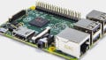
The next evolution in RPi is provided by the Model B+ single board computer. The Model B+ RPi has 4 USB ports instead of the 2 connector design of the Model B. It includes a 40 pin dual-in-line GPIO connector and a microSD card instead of the Model B's traditional bulky SD card. An HDMI connector, which is provided on the other RPI models, comes standard on the Model B+.
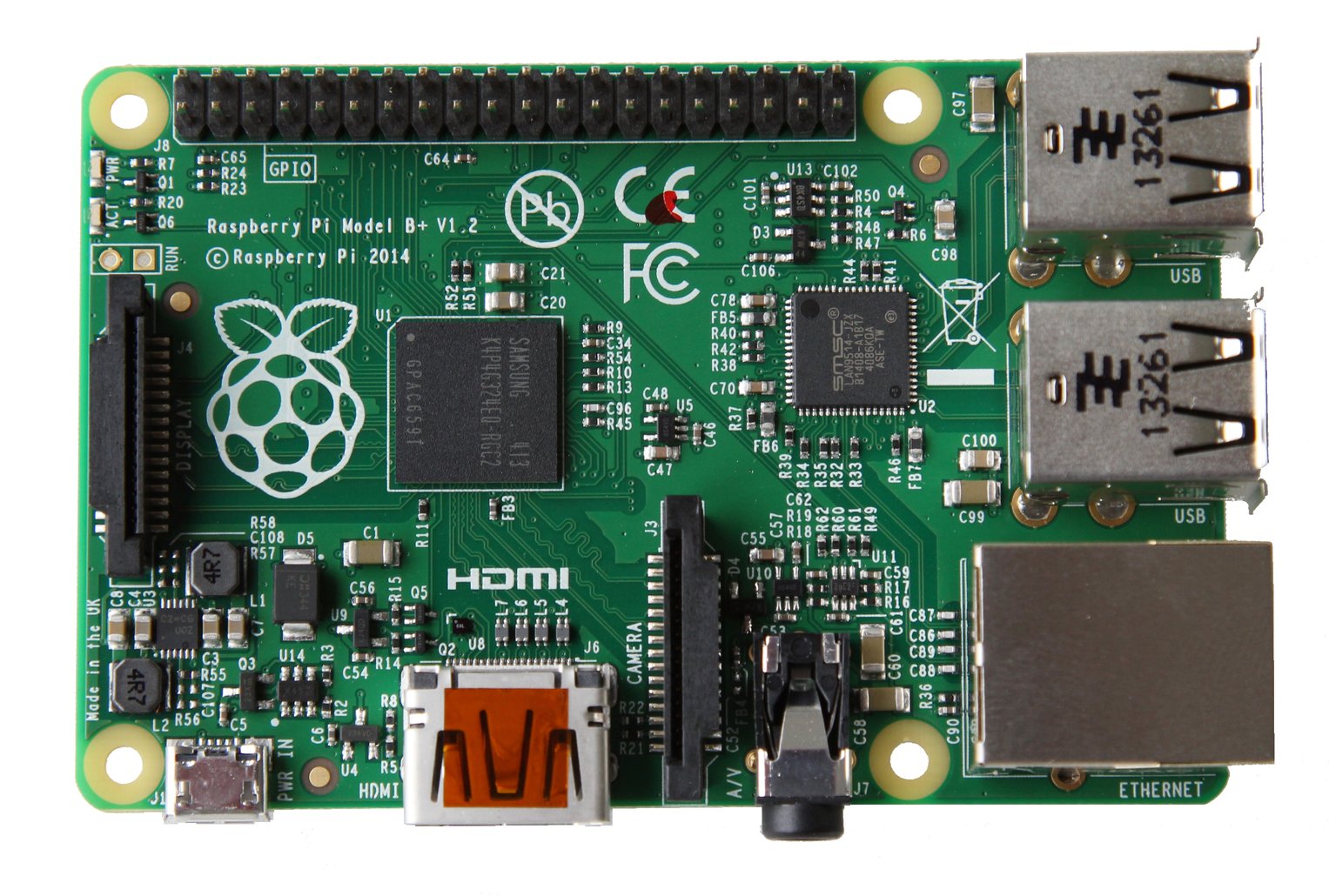
Figure 3. The Model B+ provides an accessible 40 pin dual-in-line GPIO connector with a micro SD card for Linux operating system and application files storage.
The latest RPI model, with the exclusion of the Pi zero, is the Pi 2. The Pi 2 Model B has a 1GB RAM, 900MHz quad core (BCM2836, ARM v7) processor as compared to the other RPi models using a single core ( BCM2835, ARM v6) component. The Pi 2 has the same electronics peripherals as the Model B+, thereby making pin to pin compatibility of hardware designs seamless. "However, your existing Raspberry Pi SD card images may not work because the firmware and kernel must be recompiled/adapted for the new processor," according to the adafruit website. So, firmware and Linux operating version upgrades need additional attention when performng hardware modification tasks.

Figure 4. The Pi 2 Model B with a quad core processor is the ultimate RPi Linux-based SBC.
Either one of the RPi models discussed can be used in this LED flasher project.
The RPI LED Flasher Block Diagram
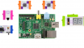
An electronic LED flasher can easily be built using a 555 Timer IC, a few resistor-capacitor components and of course an LED. The only difference between the electronic LED flasher and the RPi device is the flashing rate is adjusted using sofware instead of changing hardwired resistor-capacitor component values. There are four sub-circuit building blocks to the RPi flasher. The sub-circuit building blocks consists of a tactile pushbutton switch, a RPi, an opto-isolator, and an LED with a current limiting resistor. The RPi LED flasher block diagram is shown next.

Figure 5. The electrical-electronic components required to build an RPi LED Flasher.
I provided an enhanced block diagram of the RPi LED flasher showing the actual electrical-electronic components for the project as an additional reference.

Figure 6. A modified RPi LED Flasher block diagram with actual electrical-electronic components. Notice the input and output components wired to their associated RPi GPIO pins.
Although I used the Model B version of the RPi, you may use the other SBCs discussed for the LED flasher project as well. Now, let's move on to discussing the operation of an opto-isolator.
What is an Opto-isolator?
An opto-isolator is an electronic circuit that separates high voltage signals and sources from low voltage circuits. The technique of electrical signal isolation is accomplished by using a photodiode and a phototransistor pair. When the photodiode is wired correctly for proper operation, an invisible light or photons are emitted from the electronic device when electrical current flows through it. Forward biasing is the technical term used to describe the proper wiring and electrical current flow operation of the photodiode. The invisible light or photons hitting the phototransistor's light sensistive surface will allow it to conduct electrical current flowing from its collector lead through the emitter to ground. The electrical current flow means the phototransistor is biased correctly and will turn ON like an electronic switch. An external electrical circuit or electronic component wired to the phototransistor will turn ON as well. The applied high voltage source or signal is isolated from the low voltage circuit because of this photonic interface between the photodiode and the phototransistor. The high voltage is never electrically connected to the low voltage supply.

Figure 7. A typical electronic symbol for an opto-isolator
Using an opto-isolator in your RPi Controller projects is a nice way to use high voltage sources without damaging the SBC. The onboard +5VDC power supply will be used to increase the brightness of the LED. The opto-isolator will turn on the phototransistor which will drive the LED using the onboard +5VDC power supply on the RPI PCB. Now that you understand opto-isolator electrical theory, let's build an RPi LED flasher!.
The RPi LED Flasher Hardware
To build the RPi LED flasher is relatively easy using either a solderless breadboard wiring diagram or an electronic circuit schematic diagram. In Figures 8 and 9, I provide both diagrams. If you are learning how to wire electronic circuits, I suggest using the solderless breadboard wiring diagram to build this project. For you experienced electronics makers, the circuit schematic diagram is the preferred wiring document of choice. Notice on the solderless breadboard diagram I provide the wiring details of the opto-isolator, the tactile pushbutton switch, the current limiting resistor, the LED, and the electrical connections to the Pi cobbler. Remember to pay close attention to the Pi cobbler you are using based on your Raspberry Pi model selection for this project. The Pi cobbler pin outs are different between the RPI model sets.

Figure 8. The solderless breadboard wiring diagram to buid the RPi LED Flasher. Notice the placement of the electronic components on the solderless breadboard particularly the opto-isolator (P/N CNY74-4H-ND) and the Pi Cobbler.

Figure 9. The RPi LED Flasher electronic circuit schematic diagram
TAs additional reference material to aid in the build of the RPi LED flasher hardware, I provided the opto-isolator pin out. The frizting circuit block shown on the circuit schematic diagram unfortunately doesn't provide details of how the photodiode-phototransistor pairs/optical channels are placed inside of the 16 pin dual-in-line package (DIP). The CNY74-4H-ND opto-isolator electrical pin-out is provided in Figure 10.

Figure 10. Electrical pin out and physical package of the CNY74-4H-ND four channel opto-isolator IC (integrated circuit).
After completing the hardware build of the RPi LED Flasher, I suggest rechecking your circuit for wiring errors prior to applying power to the RPi. If there are wiring errors, correct them then apply power to the LED flasher circuit. Here's a picture of my RPi LED Flasher circuit shown in Figure 11. You can use this image as a reference model to help build your RPi LED Flasher. The final part of the project is to provide the code that will allow the device to operate properly.

Figure 11. The author's RPi LED Flasher. The author chosed to use the Model B for the project for the purpose of blowing the dust off of his first RPi SBC.
The RPi LED Flasher Python Code
The final stage of the RPi LED Flasher project is to add some Python code. To develop RPi controllers, Python scripting language is quite easy to use in reading electrical switches, electronic sensors and controlling LEDs, DC motors, and electromechanical relays. As demonstrated in the first part of this multipart series, wiring a tactile pushbutton switch and programming the RPi to read its electrical contacts status was relatively easy to do. This project is the continuation of part one where pressing the tactile pushbutton switch will allow the LED to flash at a specified rate. Releasing the pushbutton switch will stop the LED from flashing. To help explain the operation of the Python code, I provided a wealth of comment statements. Listing 1 shows the well commented RPi LED Flasher Python code. I named the Python code as pbswitch_flasher.py. Open the LXTerminal's nano or the Python IDLE editor and type the RPi LED flasher code shown in Listing 1 into the LXTerminal screen.
# *********** Pushbutton Switch LED Flasher ******************
#
# created by Don Wilcher Nov 28, 2015
#
#
# Press/hold tactile pushbutton switch, LED flashes
# Release tactile pushbutton, LED turns off

# Add libraries to python script

import RPi.GPIO as GPIO
import time

# Include BCM I/O pins into python script and define pin numbers

GPIO.setmode(GPIO.BCM)
pbswitch_pin = 4
LED_pin = 18

# Create pbswitch pin as an active low switch (use RPi internal pullup resistor)
# and define LED pin as an output

GPIO.setup(pbswitch_pin, GPIO.IN, pull_up_down = GPIO.PUD_UP)
GPIO.setup(LED_pin, GPIO.OUT)

# Define and set (initialize) the LED output state as False

LED_state = False


# pbswitch event monitoring loop: check pbswitch_pin and flashes LED output based on new input event being False

while True:
    new_input_event = GPIO.input(pbswitch_pin)
    if new_input_event == False:
        LED_state = not LED_state
        GPIO.output(LED_pin, GPIO.HIGH)
    time.sleep(.1)
        GPIO.output(LED_pin, GPIO.LOW)
    time.sleep(.1)
To run the code on your RPi, in the LXTerminal type the following linux commmand after the prompt.
pi@raspberrypi ~ sudo python pbswitch_flasher.py
Now press and hold the tactile pushbutton switch and the LED should be flashing. Congratulations on building your second RPi controller! Experiment with the flash rate by changing the value of time (in seconds) to 1 sec. The line of code to change the flash rate is shown next.
time.sleep(.1): change .1 to 1
Both lines of instruction will need to be changed to provide a balance ON/OFF flash rate. Create different flashing patterns by providing non equal timing values into the time.sleep() Python instruction. Record observations in a notebook as well as record a video clip of the working project with your smartphone. In part three of Building RPi Controllers, you'll explore how to control a small DC motor with a light sensor (photocell).
Next Article in Series: Build an Object Detection DC Motor Controller
Give this project a try for yourself! Get the BOM.