Facebook
 Google
 GitHub
 Linkedin
C-BISCUIT: Layout and Assembly for the Robot Control Board
We’ll discuss some important layout and manufacturing concepts as we look at the PCB for the Robot Control Board.
In this installment of the C-BISCUIT adventure, we’ll discuss some important layout and manufacturing concepts as we look at the PCB for the Robot Control Board.
The C-BISCUIT Series
- C-BISCUIT: A Robotics Platform for the Hacker and Hobbyist
- C-BISCUIT: Design Choices and Justification
- C-BISCUIT Power: 5V 3A Buck Regulator for Wandboard
- C-BISCUIT Power: Crowbar Protection Circuit for 5V Regulator
- C-BISCUIT: The Brains of the Operation
- C-BISCUIT Power: Assembly and Testing of Regulator and Crowbar Circuits
- C-BISCUIT: Monitoring Your Robot’s Health
- C-BISCUIT: Robot System Architecture
- C-BISCUIT: Schematic Design for the RCB—Microcontroller, Motor Controller
- C-BISCUIT: Schematic Design for the RCB—Power, Stepper
- C-BISCUIT: Layout and Assembly for the Robot Control Board
- C-BISCUIT: System Integration and Testing

Intro
The previous two articles presented and explained the various portions of the schematic for the Robot Control Board (RCB), and everything worked perfectly in the dreamy land of theoretical circuit design.
Unfortunately, we can’t control a robot with a schematic, even if you print out a hard copy. For that task we need a printed circuit board (PCB). Actually, we need much more than a PCB—we need a PCB with components properly installed. And nowadays, this is not always a straightforward task.
The Assembly Quandary
The problem, as I’m sure you know, is surface-mount technology. It is not always easy to solder surface-mount components using a soldering iron; it is far from easy to hand-solder the miniscule or very-fine-pitch surface-mount components that are all the rage these days; it is almost impossible to hand-solder those maddening leadless packages that are increasingly common; and finally, hand-soldering is a distant memory when you are dealing with land grid arrays (LGAs) or ball grid arrays (BGAs).

Image courtesy of Digi-Key. The DC/DC converter on the RCB is a (surprisingly small) land-grid-array package—I don’t think I could reach those interior terminals with my soldering iron.
One alternative is a hot-air soldering gun. These are quite effective for rework, but assembling an entire board with one could be seriously tiresome. The next option is DIY reflow; in some cases, this is a great solution. You can find an abundance of further information in previously published articles including this one, this one, and this one.
But DIY reflow is still very troublesome, if not downright impractical, with certain boards. I wouldn’t even attempt to solder a BGA or LGA in a toaster oven, and fine-pitch packages are a problem because it’s difficult to avoid solder bridges between closely spaced pins, especially if you’re applying solder paste manually (i.e., without a stencil).
And the list goes on—placing tiny passives with tweezers gets old fast, a toaster oven might not provide adequately even heating for a large PCB, you may need additional techniques to successfully reflow a board with components on both sides. . . . The bottom line is, sometimes the best approach is to hire the experts.
Professional Assembly without Breaking the Bank
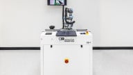
Fabrication and assembly for the C-BISCUIT Robot Control Board was officially sponsored by MacroFab. The folks at MacroFab offer what I consider to be high-quality yet affordable manufacturing services for makers, students, inventors, and even small engineering firms. In contrast to most assembly houses, they specialize in low-volume orders, so MacroFab is a practical option even if you want only one populated PCB. I haven’t done a formal comparison, but about a year ago I looked around for low-volume assembly options, and my impression was (and still is) that few if any companies offer services and prices comparable to MacroFab’s.
I won’t go into detail on MacroFab’s ordering system and file requirements, but suffice it to say that you will need to have your ducks in a row. You cannot walk up to the front desk with a cardboard box full of scavenged components and a hand-written BOM. You need manufacturing files for the PCB (because MacroFab handles board fabrication as well as assembly), a solid BOM with manufacturer part numbers, and XYRS placement data.
But honestly, this is a good thing. Formal manufacturing procedures are not annoyances that big engineering companies have to put up with; rather, they have become integral aspects of well-organized, successful board design. Working with MacroFab’s online ordering system—which is comprehensive yet still intuitive—will encourage you to make your design practices more efficient and reliable.

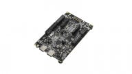
A very clean assembly job, and I like MacroFab’s standard red-and-white styling. When entering all the data for my order, I flagged the through-hole line items as “do not populate”—I can take care of those with my soldering iron, and I knew that some of the through-hole parts wouldn’t be necessary for the initial demo bot.
The Layout
Here is the RCB as it appears in my layout software (I use DipTrace).

I’ll mention a few salient issues here, then I’ll discuss a couple portions of the layout in greater detail.
- Note the fiducials, labeled FID1, FID2, etc. These facilitate the assembly process. You can read more about fiducials here.
- It’s a good idea to use different display colors for different nets. This is especially helpful with power and ground connections. Here I have a brown/orange color for ground, bright green for +3.3V, a softer green for +12V, and yellow for +5V. All other nets are displayed as red on the top layer and bright blue on the bottom layer.
- This is a typical four-layer stack-up: top and bottom for components and routing, one plane layer dedicated entirely to ground, and one plane layer used primarily for the three power-supply voltages.
- I do not use thermal relief (aka “thermals” or “spokes”) for via and through-hole connections to plane layers or copper pours. (See the image below for an example.)
- Thermals may be enabled by default in your layout software. Nevertheless, in my opinion, thermals are usually undesirable. They limit the flow of heat from the hole to the surrounding copper. This is handy when you’re using a soldering iron, but with reflow, the entire board gets heated up, so thermals are not necessary. Furthermore, we often want vias to move heat away from components, such as with exposed-pad (e.g., DFN and QFN) packages, so in these situations thermals are working against you.
- Another disadvantage is that thermals can lead to awkward copper arrangements, for example when several vias in close proximity must connect to the same plane layer. And hand-soldering is by no means impossible when a through-hole is connected to a plane layer without thermals, though it does require some patience.

This via is connected to the surrounding copper using “spokes” for thermal relief. This facilitates hand-soldering, but in general you don't need (or want) thermals if the board will be assembled using reflow soldering.
Current Rating vs. Thermal Shutdown
As you know, this board includes two MAX14870 motor-driver ICs. These devices are rated for 2.5 A peak motor-drive current. But that is only the maximum current rating; how much motor current you can actually deliver in your particular circumstances is a more complicated issue.
The trouble is, current doesn’t exist in isolation. If current is flowing through resistance, you also have power dissipation, and if you have power dissipation, you have heat. And if the chip gets too hot, it shuts down.
The MAX14870 incorporates nontrivial resistance in the form of the on-state resistance of the H-bridge FETs. So, you cannot simply solder the MAX14870 to a PCB, crank the current up to 2.5 A, and walk away. If your PCB doesn’t encourage heat to move away from the IC and into the ambient environment, the part could eventually go into thermal shutdown—this can occur quite rapidly at 2.5 A, or it could take a minute or two at lower currents.
Thus, careful PCB layout is an integral aspect of properly implementing the MAX14870 and many other high-power devices. An external heatsink is usually not a convenient solution, so instead we use vias and large copper areas:

Notice that the copper pour coming up from below the MAX14870 (U7) is not electrically connected to the U7 pour. That’s because it belongs to the exposed pad of another motor-driver IC. It’s the same ground, so I could have connected them together, but this way I might be able to gather some information on how much copper and how many vias are needed to get adequate performance out of the MAX14870.
The package’s exposed pad is designed for heat removal, and we can make the most of this feature by connecting the exposed pad to a large copper pour, which helps to move heat from the MAX14870 to the surrounding air. The copper pour also has via connections to the ground plane; these will move heat from the chip to the ground plane, and from the ground plane to other parts of the PCB and to the ambient environment.
This layout was somewhat crowded, so I had to be creative in filling available space with copper. But even if you don’t have a lot of extra room for top-layer copper, you can still squeeze in numerous vias to help move heat to the ground plane or to copper pours on the bottom of the board.
Copper, Vias: Good for Heat Flow and Current Flow
I also like to use generous amounts of copper whenever I expect large or rapidly changing currents. Don’t be stingy here—the board house won’t give you a discount for allowing more of your board’s copper to be etched away. Wide traces, large pours, and multiple vias all help to reduce resistance and inductance.
Inductance is particularly troublesome because of its frequency-dependent behavior; it interferes with rapid bursts of current (which are required by digital ICs) and other high-frequency action, and thus it can lead to performance issues that are difficult to diagnose or even recognize.
The following is the layout I used for the DC/DC converter circuit.

Note the large copper pours and numerous vias used for the ground and +12V connections. The +5V connection also has plenty of copper, but I didn’t use vias there because the plane area underneath the pour is connected to +12V, not +5V.
Low inductance (and resistance) is critical when you’re laying out decoupling capacitors for high-speed digital ICs. The RCB doesn’t have any really-high-frequency circuitry, but that’s no reason to dispense with good layout practices. The following image shows the layout for the microcontroller’s decoupling caps.

Conclusion
At this point you know quite a bit about how I designed and manufactured the C-BISCUIT Robot Control Board—actually, I didn’t manufacture it, MacroFab did. In the next article, we’ll look at system integration, i.e., forcing the various components to actually cooperate so that we have a functional demo bot.
Next Article in Series: C-BISCUIT: System Integration and Testing