Facebook
 Google
 GitHub
 Linkedin
C-BISCUIT: Robot System Architecture
The C-BISCUIT saga continues as we combine the various system components into a demo bot.
The C-BISCUIT saga continues as we combine the various system components into a demo bot.
The C-BISCUIT Series
- C-BISCUIT: A Robotics Platform for the Hacker and Hobbyist
- C-BISCUIT: Design Choices and Justification
- C-BISCUIT Power: 5V 3A Buck Regulator for Wandboard
- C-BISCUIT Power: Crowbar Protection Circuit for 5V Regulator
- C-BISCUIT: The Brains of the Operation
- C-BISCUIT Power: Assembly and Testing of Regulator and Crowbar Circuits
- C-BISCUIT: Monitoring Your Robot’s Health
- C-BISCUIT: Robot System Architecture
- C-BISCUIT: Schematic Design for the RCB—Microcontroller, Motor Controller
- C-BISCUIT: Schematic Design for the RCB—Power, Stepper
- C-BISCUIT: Layout and Assembly for the Robot Control Board
- C-BISCUIT: System Integration and Testing
Refresher and Intro
C-BISCUIT stands for Collaborative Bot with Integrated System Core, Unmanned Interactivity, and Telemetry. It is intended to be more of a platform for robotics projects, not a specific robot. This platform is based on the Wandboard Quad, which is essentially a low-cost embedded computer with impressive processing and input/output capabilities. The Wandboard can run Linux as well as the Robot Operating System (ROS), which is an open-source collection of software tools that can help ordinary folks explore robot development.
However, we need to test and demonstrate the platform, and for that we need an actual robot. The previous articles in the C-BISCUIT series have discussed various components of the overall project—for example, the power supply, the software setup, the camera—as well as the overall system design.
At this point, it is time to finalize the system architecture and integrate the components into a well-oiled machine!
As is often the case in life, the final version does not look exactly like what was originally planned. If you review the previous articles, you’ll see that we are attempting to incorporate some improvements that will result in a more visually appealing robot with a more streamlined system design.
Updated Architecture
At this point the primary components of the demo bot are the following:
- Lynxmotion Tri-Track robot chassis
- Wandboard Quad, with enclosure and SD card loaded with ROS
- Wandboard antenna kit for Wi-Fi communication
- WandCam (a 5-megapixel camera that is designed for direct interfacing to the Wandboard)
- 12 V, 2800 mAh NiMH battery pack
- Battery charger
- Robot Control Board, a custom-designed PCB
Here is a system diagram:

Now let’s take a look at each one of the system components.
A Frame for the Bot
There’s not much to say about the Tri-Track. We like the tank-style treads, we like the way it looks, we like that it has only two motors, and it seems spacious enough for the C-BISCUIT hardware.
A Brain for the Bot
The Wandboard is covered in previous C-BISCUIT articles, so we don’t need to dwell on it here. In the demo bot, the Wandboard is responsible primarily for two things: receiving image data from the WandCam and transferring this data over Wi-Fi to a laptop that will display the imagery.
Eventually we want to implement machine-vision algorithms that will allow the Wandboard to influence the robot’s behavior based on input from the camera. The Wandboard has an RF connector that allows us to use a separate antenna mounted in a convenient location.

Vision for the Bot
The WandCam is discussed in C-BISCUIT: Design Choices and Justification. As of this article’s writing, we’re having some difficulties getting image data from the Wandboard to the PC, and it’s possible that we’ll try a different camera as a workaround.
Powering the Bot
The original plan for the power source was an 11.1 V, 5000 mAh lithium polymer (LiPo) battery. There is nothing specifically wrong with this choice and maybe we will return to LiPo if we are not satisfied with the 2800 mAh available from the NiMH battery mentioned above. However, the following considerations argue in favor of NiMH over LiPo:
- The Tri-Track robot chassis comes with 12 V motors. It’s preferable to operate a motor at its specified voltage, and this is not so easy with LiPo because LiPo-pack voltages come in increments of 3.7 V (one LiPo cell generates 3.7 V). So if you’re looking for 12 V, the closest you can get is a three-cell pack that provides 11.1 V.
- LiPo batteries are more finicky when it comes to charging, storage, and transportation, and they are generally considered more dangerous because they have a tendency to explode under seriously adverse conditions.
- NiMH batteries endure more charging cycles than LiPo. We might be doing a lot of charging and discharging as we pull this demo bot together, and I like the idea of a longer-lasting power source.
It would be convenient to integrate battery-charging capability into the robot’s electronics; that way we could recharge the battery through a USB connection that is also used for communication between the robot and a PC. But that bonus feature didn’t make it in, and instead we have an off-the-shelf charger that will do the job nicely.
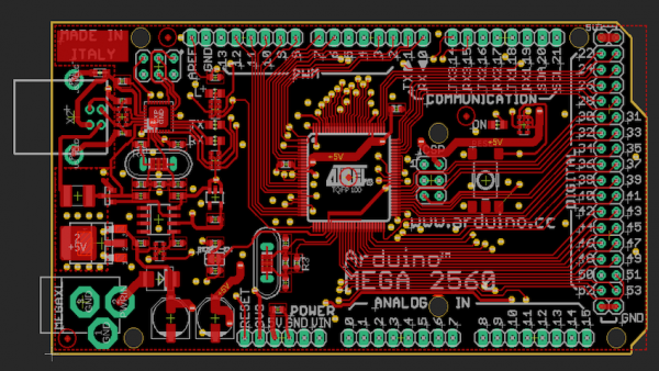
Controlling the Bot
Our idea here is to incorporate all necessary control and power circuitry into one custom-designed PCB. This will make for a cleaner overall solution—i.e., less wiring, fewer circuit boards to secure to the chassis, tighter integration, and greater customization. The Robot Control Board (RCB) has the following requirements:
- Communicate with the Wandboard
- Control the motors that move the robot chassis
- Convert 12 V from the battery to 5 V for the Wandboard and for the low-voltage circuitry on the RCB
- Monitor the battery voltage
Wandboard Comms
Wandboard communication will be available via USB and logic-level UART.
In the long term, USB is the preferred option, for a few reasons:
- The Wandboard has a standard USB connector, whereas the UART signals used for RCB communication are available only as test points.
- Properly shielded USB cables are readily available.
- USB employs differential signaling and incorporates a cyclic redundancy check (CRC) for error detection.
I usually wouldn’t place much emphasis on 2) and 3), but we’ll have motor-drive currents switching on and off, and in my opinion that translates to a rather noisy environment for electronics. With shielding, differential signaling, and CRC, USB is more likely to provide a robust communication interface compared to the UART’s single-ended, 3.3 V ribbon-cable connections.
However, USB cannot compete with UART when it comes to firmware/software simplicity. I can handle some microcontroller USB development, but I know precisely nothing about implementing USB communication in Linux, so I want to make sure that we have UART as a backup.
Motor Control
The robot chassis comes with two 12 V brushed DC motors. The RCB will control these using motor-drive ICs that allow us to easily implement forward/backward rotation, PWM speed control, and current limiting.

Image courtesy of RobotShop.
At one point we were hoping to find a suitable robot chassis that comes with stepper motors instead of brushed DC motors, but that search proved futile. Stepper motors allow for high-precision movements, but controlling them is more complicated, and this added complexity might partly explain the shortage of stepper-based chassis options. We didn’t want to give up on the possibility of a stepper-motor-based robot, though, so we decided to incorporate stepper-drive functionality into the RCB.
At this point, it seems more likely that we will use the stepper-drive circuitry for additional robot features rather than for moving the robot itself.
Regulating Voltage
The battery gives us 12 V, but we need 5 V for the Wandboard. It would also be handy to have 5 V for the RCB’s logic-level circuitry because we’re using an EFM8 microcontroller that has an on-chip 5 V–to–3.3 V linear regulator.
The Wandboard has fairly high current requirements—the user guide recommends a power supply that can source at least 2 A. Thus, a linear regulator is not the best choice; we want the efficiency of a switching regulator, and to simplify the design process on our end we will employ a µModule DC/DC converter from Linear Technology.

Linear Tech’s conception of why you might opt for a µModule, taken from the µModule product guide. I find this image highly amusing, and to be honest it’s a pretty good visual representation of how I feel about custom-designed switching regulators.
Proper Care of NiMH Batteries
The microcontroller’s analog-to-digital converter will be used to monitor the voltage coming from the battery. I think most designers would intuitively recognize the need to ensure that a battery-powered system is aware of the voltage being produced by its power source. But the importance of battery monitoring goes beyond this when we’re dealing with rechargeable batteries because excessive discharge can actually damage the battery.
The voltage across the battery decreases as it supplies current to the system; the following diagram, taken from Energizer’s NiMH Handbook and Application Manual, depicts the typical discharge profile for a NiMH cell.

Image courtesy of Energizer
If the microcontroller knows the battery voltage, it can use this curve to estimate the discharge percentage, and then it can take action to prevent excessive discharge. The Energizer document states the following: “To prevent the potential for irreversible harm to the battery . . . removal of the load from the battery prior to total discharge is highly recommended.”
Some Google searching indicates that a NiMH battery pack should not be discharged beyond 0.9 V per cell, though 1.0 V or 1.1 V might be safer. If we use 1.1 V per cell as the cutoff, we will need to shut down the robot when our ten-cell battery voltage reaches 11 V.
If you look back at the discharge profile, you can see that there is no need to push the cutoff to the absolute minimum because the voltage drops off so rapidly after about 1.1 V. Bottom line, I’d rather shut down the bot a little prematurely than risk damage to the battery.
Conclusion
We now have a bird’s-eye view of the updated system design for the C-BISCUIT demonstration robot. Stay tuned for future articles, which will explore the various parts of the bot in greater detail.
Next Article in Series: C-BISCUIT: Schematic Design for the RCB—Microcontroller, Motor Controller
Give this project a try for yourself! Get the BOM.