 Facebook
 Google
 GitHub
 Linkedin
Communicating with an EFM8 Microcontroller via USB
Many embedded applications benefit from a communications interface that allows for convenient data transfer between a PC and a microcontroller. This article explains how to use the virtual COM port library from Silicon Laboratories to send data from a Windows application to an EFM8 microcontroller.
Learn how to send data from a PC to an EFM8 microcontroller using a standard USB interface.
Recommended Level
Intermediate
Previous Articles in This Series
- The EFM8 Series from Silicon Laboratories: A Powerful New Embedded Development Platform
- Controlling an LCD via SPI: An Introduction to Project Development with an EFM8 Microcontroller
- Displaying Characters on an LCD with an EFM8 Microcontroller
Required Hardware/Software
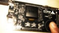
- SLSTK2000A EFM8 evaluation board
- Simplicity Studio integrated development environment
- Scilab
Project Overview
A straightforward, reliable communications link between a microcontroller and a PC can add powerful functionality to a wide variety of embedded applications—you could upload sensor data to a PC for analysis, send commands from a graphical user interface, or even incorporate a boot loading feature that makes it possible to update firmware without a typical debug interface. Not too long ago, the standard choice for this functionality was a computer’s “serial port,” which is an exceedingly vague term that refers to a universal asynchronous receiver/transmitter (UART) designed for RS-232 signal characteristics. Nowadays, though, using a serial port to communicate with a microcontroller is perhaps equivalent to plowing a field with a team of oxen—the oxen are simple beasts and they get the job done, but few would choose them over the latest GPS-guided mega-tractor.
Preferences aside, RS-232 is becoming less practical simply because the serial port is no longer a standard feature on many computers—not to mention tablets and smartphones. The choice, then, falls to USB, which of course is far superior to RS-232 in the context of modern consumer electronics. Embedded developers, though, don’t always need USB’s sophisticated features, and more importantly, implementation complexity undergoes a quantum leap when you move from serial port to USB.
Fortunately for ordinary EFM8 developers, the path to embedded USB connectivity has been cleared and leveled by experts at Silicon Laboratories. In this project, we will make use of the VCPXpress library, which vastly simplifies the process of establishing a virtual COM port (VCP) connection between Windows and an EFM8 microcontroller. VCP functionality is ideal for embedded projects that need a straightforward communications link because the USB device enumerates as a COM port, and thus bytes can be transmitted and received using standard serial port software routines.
The basic objective of this project is to successfully establish VCP communications between a PC and an EFM8 microcontroller. We will use a Scilab script to send ASCII data to the EFM8, and then the EFM8 will display the corresponding characters on the LCD using the techniques discussed in the previous article.
Port I/O
The port I/O configuration is identical to what we used in the previous article.

The SPI signals are mapped to the appropriate port pins, except for the chip select signal, which we drive manually via P0.1. We do not need to directly configure the port pins for the USB data lines; all USB peripheral initialization is accomplished through the VCPXpress library.
Peripherals and Interrupts
The peripheral and interrupt setup is similar to what we used previously: SPI is configured for communication with the LCD module, and Timer4 is used for short delays. We do not use Timer2 in this project because we have no need for a frame rate. Rather, the LCD is updated whenever the microcontroller receives a USB data packet.
Firmware
The low-level LCD interface developed for the previous project is used for this project as well. When the EFM8 receives a data packet from the PC, it clears the LCD then prints the received characters. In the previous project, the LCD display was limited to the first 60 lines on account of memory restrictions; this time only 40 lines are used because additional RAM is required for the VCPXpress library.
To create a VCPXpress application in Simplicity Studio, first create a new project as usual and then incorporate any existing source files or code blocks. Here is an important tip: though your intuition might persuade you otherwise, do not check the box next to “USB Library”:

Checking this box will cause Simplicity Studio to incorporate library files and configuration code that you do not need and, worse, that can actually conflict with the VCPXpress library.
You will need to add the VCPXpress library to your project. Right click on the project name in the Project Explorer pane, and select Properties. Go to C/C++ General > Paths and Symbols. Select the “Libraries” tab and add VCPXpress.lib:

Then go to the “Includes” tab and add the VCPXpress include directory:

There are also some files that you need to include in your project: VCPXpress.h and VCPXpress.lib are the library files, and descriptor.h and descriptor.c are involved in initializing the USB interface. You can find all four in the zipped project files:
One more project configuration tip: When you build a VCPXpress project, it is likely (perhaps certain) that you will get some linker warnings that look like this:

These warnings do not necessarily mean that there is a problem with your code, and you can suppress them as follows: Right click on the project name, and select Properties. Go to C/C++ Build > Settings and select the “Tool Settings” tab. Click on “Miscellaneous” under “Keil 8051 Linker” and paste “OVERLAY(?PR?_USB_WRITEFIFO?EFM8_USBDEP ! *, ?PR?_USBD_READ?EFM8_USBD ! *, ?PR?_USBD_WRITE?EFM8_USBD ! *, ?PR?_VCPXCORE_WRITE?VCPXPRESS ! *)” into the “Additional Flags” text box:

If you click on “Keil 8051 Linker,” you should see this:

Surprisingly little code is required to implement basic VCPXpress functionality. One function call is required to initialize the USB interface and one to configure the USB interrupt handler: USB_Init(&InitStruct) and API_Callback_Enable(myAPICallback); both of these are found in USBVCPCommunication_main.c. The code for handling received USB packets is in USBInterface.c:
VCPXpress_API_CALLBACK(myAPICallback)
{
   uint32_t API_InterruptCode;

   //get the code that indicates the reason for the interrupt
   API_InterruptCode = Get_Callback_Source();

   //if the USB connection was just opened
   if (API_InterruptCode & DEVICE_OPEN)
   {
	   //start the first USB read procedure
	   Block_Read(USBRxPacket, USB_PACKET_SIZE, &USBBytesReceived);
	   /*we will process the received bytes when we get
	   a callback with an RX_COMPLETE interrupt code*/
   }

   if (API_InterruptCode & RX_COMPLETE)   // USB read complete
   {
	   /*this flag tells the while loop in USBVCPCommunication_main.c
	     to process a received USB packet*/
	   USB_PACKET_RECEIVED = TRUE;

	   //continue with the next USB read procedure
	   Block_Read(USBRxPacket, USB_PACKET_SIZE, &USBBytesReceived);
   }

}
As indicated by the above code, USB events are handled via this “callback” function. A callback function is similar to an interrupt service routine (ISR). When an interrupt event occurs, hardware causes the processor to execute code in the ISR. A callback is essentially a higher-level software-driven ISR: interrupt events are handled by the library, and the library directs the processor to the callback function if an event requires attention from the application firmware.
The Block_Read() function is used to initiate the process of receiving data from the PC. When a USB packet is received, the firmware will execute VCPXpress_API_CALLBACK(), and the interrupt code will indicate that USB data is ready to be processed.
The “EFM8UB1 Peripheral Driver Library” provides the documentation for the functions and macros through which your code interacts with the VCPXpress library. You can access this information by clicking on “Software Documentation” in Simplicity Studio:

A USB Device Needs a USB Host
We could use a simple terminal program to send and receive VCP data, but we will use Scilab instead—a baseline Scilab-to-EFM8 interface will come in handy for future projects. You will need to download the Scilab Serial Port Library; instructions for installing and using the library are included in the downloaded zip file. The following code is used to send an ASCII string to the EFM8:
COMPort_Number = 4;

cd "C:\Program Files\scilab-5.5.2\";

exec("C:\Program Files\scilab-5.5.2\slLoadLib.sci");

clc();

EFM8Port = slMount();

slConfig(EFM8Port, 115200, 8, 0, 1);

return_val = slOpen(EFM8Port, COMPort_Number);

if return_val == 0
    printf("Unable to open COM port %d\n", COMPort_Number);
    slUMount(EFM8Port);
    slUnload();

else
    while 1
        CharsToSend = input("Send this string to the EFM8:", "string");

        if(CharsToSend == " ")
            break;
        end

        slSendArray(EFM8Port, ascii(CharsToSend), length(CharsToSend));
    end

    slClose(EFM8Port);
    slUMount(EFM8Port);
    slUnload();
end
When you run the script, the Scilab console is cleared and prompts you for input with “Send this string to the EFM8:” (keep in mind that the firmware provided here supports only the 26 uppercase letters and the space character). Type some text and press enter to send. The script repeatedly prompts for a new string until you press the return key without entering any other characters.
Testing the System
Here is the procedure for testing the communication link:
- Build the “USBVCPCommunication” project and load the code into the EFM8.
- Disconnect the mini USB cable that plugs into the connector labeled “DBG,” then move the power switch to “USB.”
- Connect a USB cable from your computer to the micro USB connector (near the joystick).
- Look in the Windows device manager to determine the COM port number for your VCP connection, and modify the Scilab script accordingly.

-
Run the Scilab script and type some characters to send. After you press enter, the characters should appear on the LCD.
Next Article in Series: How to Display an Image on an LCD using an EFM8 Microcontroller
Give this project a try for yourself! Get the BOM.
Related Content


One note, this is not for just any efm8, this is only for the Universal Bee (USB-capable) efm8 chips.