 Facebook
 Google
 GitHub
 Linkedin
Create a Two-Channel Remote Control with the nRF24L01+
This article will give you the building blocks needed to create your own two-channel wireless remote controller.
Learn how to connect an nRF24L01+, two Arduinos, and a joystick to create your own two-channel wireless remote controller.
The nRF24L01+ is an inexpensive 2.4 GHz wireless transceiver that interfaces with many microcontrollers.
This project will use an nRF24L01+ to wirelessly connect a joystick to two servos. We will start with one joystick controlling two servos on one board, then we will separate the circuit into two boards. One board will read the joystick data and transmit it to a second board that receives the data and controls the servos.
Materials Used
Joystick Option 1 — Variable Resistor Joystick
Most of the two-axis joysticks available for hobby use move center-tapped potentiometers that convert mechanical displacement to variable resistance.
For a $$10\;k\Omega$$ resistor, a centered position would correspond to $$R=5\;k\Omega$$, far right would correspond to $$R=10\;k\Omega$$ and far left would correspond to $$R=0\;k\Omega$$. Similar values would correspond to the up and down direction.

Unfortunately, microcontrollers do not directly measure resistance. They do directly interpret potential difference above their 0 V reference on their input lines, so some minor effort must be made to use a variable resistance to create a variable potential difference.
Create a known constant potential difference across the outer pins of a variable resistor and the potential difference measured between the center wiper and ground will be proportional to the displacement, varying between 0V and 5V.

These joysticks are inexpensive and plentiful. But contact joysticks have limitations. Dirt, oxidation, moisture, or physical wear can cause fluctuations in readings across the contacts. This isn't a problem for a battle bot, but it is certainly a problem in safety-critical or precision applications where slight variations can cause uncommanded movement.
For a two-axis joystick, you'll need two available analog pins to read the joystick, one for each axis.
Connecting a joystick to an Arduino is quite easy: GND, 5V, A0 for fore/aft, A1 for left/right. Expected potential differences range from very near 0 V to very near 5 V.

Joystick Option 2 — Contactless Joystick

Electric wheelchairs and high-end industrial equipment have very nice contactless joysticks that can also be interfaced with the same four wires: A ground reference, a 5 volt potential difference from ground, and two analog potential difference outputs corresponding to the Forward/Aft and Left/Right directions. The outputs are influenced by the movement of magnets near a hall-effect sensor.
There is no functional difference in computer code, nor is there any change in the number of inputs used. The only difference between the previous joystick and this one is that the range in potential differences decreases—however, the range is still within 0 to 5 V.
These contactless joysticks have no touching parts to corrode, wear, or degrade. They can function in damp environments and are all but bulletproof in their reliability. However, they come at a cost more than 20 times higher than joysticks with contacts.
Either type of joystick may have multiple pins on its interface, but most joysticks require only four pins to interface with the Arduino.

| Arduino Pin | Resistive Joystick | Contactless Joystick |
|---|---|---|
| Gnd | Gnd | Gnd |
| 5 VDC | L/R+ & U/D+ | 5 VDC |
| A0 | U/D | Fore / Aft 1 |
| A1 | L/R | Left / Right 1 |
Reading Data from a Joystick
Whenever I'm constructing a complicated circuit, I like to do it a bit at a time and keep track of the values for that small bit. The first step in our workflow is to read data from a joystick. I used a contactless joystick; if you use a resistor-based joystick, your values will change.
The following code should keep track of the values and send data from the joystick through the Arduino Uno to the terminal to verify everything is working correctly:
//Code to control servos with joystick

int ForeAft_Pin = 0;       // Fore / Aft input is Arduino pin A0
int LeftRight_Pin = 1;     // Left / Right input is Arduino pin A1

int ForeAft_Input;         // Expected Range 220-800 for a hall-effect joystick
int LeftRight_Input;       // Expected Range 220-800 for a hall-effect joystick

void setup()               // Main Program Initialization
  {
    Serial.begin(9600);    // Prepare debug
  }

void loop()
  {
    ForeAft_Input = analogRead(ForeAft_Pin) ;          // Read Fore/Aft Value
    LeftRight_Input = analogRead(LeftRight_Pin) ;      // Read Left/Right Value

    Serial.print(LeftRight_Input);                     // Send Left/Right to terminal
    Serial.print("\t");
    Serial.println(ForeAft_Input);                     // Send Fore/Aft to terminal

    delay( 1000 );                                     // Wait 1 second before looping
  }
I also like to know what values are reasonable and what values are not as that can give me critical information when it comes to troubleshooting. The range of reasonable values dictates the types of variables to use and determines which values should cause the program to recognize an error and halt execution.
Note that error correction has not been included in the program.
Creating Servo Output
After you've read the joystick position and verified it in the debug terminal, you will need to note the limits of each axis and incorporate them into the next bit of code. This step is needed to ensure that the far left position of the joystick corresponds to the counterclockwise limit of the servo, and the far right position of the joystick corresponds to the full clockwise limit of the servo.
Next, we will add two servos to the circuit. Connect the ground lines and the 5VDC lines to the Arduino. Then connect one servo's signal line to digital out pin 6 and another to digital out pin 7.

The next bit of code is going to read the joystick position and convert it to a corresponding angle $$0^\circ<\theta<180^\circ$$ and send the appropriate signal to the servo:
#include <Servo.h>
// Servo.h code that creates two servo variables -- one for each axis of the joystick
Servo ForeAft;              // Define a Servo for Forward and Reverse Motion
Servo LeftRight;            // Define a Servo for Left and Right Motion
// Decide where you are going to plug the joystick into the circuit board.
int ForeAft_Pin = 0;        // Plug Joystick Fore/Aft into Analog pin 0
int LeftRight_Pin = 1;      // Plug Joystick Left/Right into Analog pin 1
// Create variables to read joystick values
float ForeAft_Input ;       // Variable to store data for Fore/Aft input from joystick
float LeftRight_Input ;     // Variable to store data for Left/Right input from joystick
// Create variables to transmit servo value
int ForeAft_Output;         // Expected range 0 - 180 degrees
int LeftRight_Output;       // Expected range 0 - 180 degrees
// These variables allow for math conversions and later error checking as the program evolves.
int Fore_Limit = 800;       // Joystick limit up
int Aft_Limit = 220;        // Joystick limit down
int Right_Limit = 800;      // Joystick limit right
int Left_Limit = 226;       // Joystick limit left
void setup()                // Main Program Initialization
{
    Serial.begin(9600);     // Send data back for debugging purposes
    ForeAft.attach(6);      // Plug a servo signal line into digital output pin 6
    LeftRight.attach(7);    // Plug a servo signal line into digital output pin 7
}
void loop()
{
    ForeAft_Input = analogRead(ForeAft_Pin) ;              // Read the Fore/Aft joystick value
    LeftRight_Input = analogRead(LeftRight_Pin) ;         // Read the Left/Right joystick value
    ForeAft_Output = convertForeAftToServo(ForeAft_Input) ;        // Convert the Fore/Aft joystick value to a Servo value (0-180)
    LeftRight_Output = convertLeftRightToServo(LeftRight_Input) ;  // Convert the Left/Right joystick value to a Servo value (0-180)

    Serial.print(ForeAft_Output);        //Debug
    Serial.print("\t");                  //Debug
    Serial.println(LeftRight_Output);    //Debug

    ForeAft.write(ForeAft_Output);                        // Command the Fore/Aft servo to a position
    LeftRight.write(LeftRight_Output);                    // Command the Left/Right servo to a position
    delay( 100 );                                    // Increase for debug, decrease to reduce servo jitter
}

// Functions to convert and scale the Fore/Aft and Left/Right data

float convertForeAftToServo(float y) {
  int result;
  result = map(y, Aft_Limit, Fore_Limit, 0, 180);
}

float convertLeftRightToServo(float x){
  int result;
  result = map(x, Left_Limit, Right_Limit, 0, 180);
}


// map() truncates data -- if you need a bit more accuracy for some reason, these
// functions should give it to you.
//
// float convertForeAftToServo(float y) {
//   float result;
//   result = ((y - Aft_Limit) / (Fore_Limit - Aft_Limit) * 180);
//   return result;
// }
//
// float convertLeftRightToServo(float x) {
//   float result;
//   result = ((x - Left_Limit) / (Right_Limit - Left_Limit) * 180);
//   return result;
// }
//
Here's a video of the joystick/ servo connection in action:
The nRF24L01+
The nRF24L01+ is a half-duplex transceiver that you can connect to your Arduino, Raspberry Pi, or other microcontroller to send bi-directional information. It operates in the 2.4 GHz ISM (Industrial, Scientific, and Medical) band.

Image captured with a Tektronix MDO 3104 mixed domain oscilloscope
The pros are that it works well, has low power consumption, is easy to use, and is an extremely inexpensive way to send and receive information. You can power it directly off of the Arduino's 3.3V regulated output, or the 5V regulated output if you use the base.
The cons are that it uses several IO pins to function as intended, it cannot send/receive simultaneously, the 2x4 8 position header is minorly inconvenient to use, and $$V_{DD}$$ cannot exceed 3.6 V, with 3.0 recommended, and the range is somewhat limited.
The pros far outweigh the cons. Buy a fistful of these on eBay or from addicore and add wireless to your projects in little to no time at all.

nRF24L01+ base (left) with nRF24L01+ half-duplex transceiver (right)

nRF24L01+ mounted in base module
You will find that the base module for the nRF24L01+ is easier to use while prototyping, as it handles voltage regulation and filter capacitors for the nRF24L01+
Note that the base unit requires 5V while the nRF24L01+ requires 3.3V.

Homemade pin-swap board, nRF24L01 base, and nRF24L01+ transceiver
This article is about using the nRF24L01+, and you can hook it up directly to an Arduino with the diagrams below. However, I quickly found the multiple wires were quite inconvenient and knew that if I put this project in a drawer and took it back out to work on it later, half of the wires would be unplugged which wastes time and leads to errors. So I chose to use the project with a modified base module and a home-made pin-swap board.
I modified the base module by adding full-length pass-through male headers—my plan at the time was to plug it directly into the Arduino Uno R3. However, the pins on the base-module do not correspond to the pin designations in the libraries. So I also created a homemade pin-swap board that interfaced the base module with my Arduino rather than change the code in the libraries. This allows me the convenience of plug-and-go hookup while maintaining full compatibility with readers who do not want to do the modifications.

nRF24L01+ mounted in base-unit, mounted in home-made adapter board, mounted in Arduino Uno R3
Note: There are many great how-to articles written on how to implement these wireless modules in your designs and how to troubleshoot when things go wrong. I don't have anything worthwhile to add to them in this article, so instead, I'd like to refer you to this page for troubleshooting and additional information.
Connecting the Arduinos
First, download and install these libraries for your Arduino.
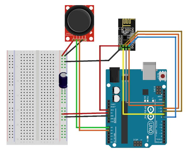
Then make the following connections between the nRF24L01+ and your Arduino:
| Pin | nRF24L0+ | Arduino Uno R3 |
| 1 | Gnd | Gnd |
| 2 | Vcc | Vcc |
| 3 | CE | Digital 9 |
| 4 | CSN | Digital 10 |
| 5 | SCK | Digital 13 |
| 6 | MOSI | Digital 11 |
| 7 | MISO | Digital 12 |
| 8 | IRQ | Digital 8 |

Delivering consistent power to the nRF24L01+ carrier board is essential. If you have trouble getting your nRF24L01+ to work, and you've verified the wires and the code, try using an oscilloscope to trace whether or not the 3.3 V output is consistent. If it is not:
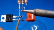
- Add filter capacitors to your circuit. Use jumper wires, small alligator clips, or other means to attach a 0.1 µF - 10 µF capacitor to the power leads near the nRF24L01+ carrier board.
- Disconnect from USB power and use 4 AA batteries to power your Arduino through the barrel jack connector (4x1.5 V=6 V).
Next, you'll want to follow these steps:
- Set up two Arduinos with nRF24L01+ wired to them.
- Copy the "Getting Started Code" below into a sketch, or open it from the examples library (after you've installed the libraries).
- Change line 15 to "RF24 radio(9,10);"
- Upload the Getting Started Code to the first Arduino with line 12 reading "bool radioNumber = 0;"
- Upload the Getting Started Code to the second Arduino with line 12 reading "bool radioNumber = 1;"
- Then open two terminals: one to connect to the first Arduino and one to connect to the second. Type "T" as instructed in one terminal. Numbers will start bouncing back and forth between the two transceivers. This lets you know that you've hooked up everything correctly and that everything is working.
/*
* Getting Started example sketch for nRF24L01+ radios
* This is a very basic example of how to send data from one node to another
* Updated: Dec 2014 by TMRh20
*/
#include <SPI.h>
#include <RF24.h>
/****************** User Config ***************************/
/***      Set this radio as radio number 0 or 1         ***/
bool radioNumber = 0;
/* Hardware configuration: Set up nRF24L01 radio on SPI bus plus pins 7 & 8 */
RF24 radio(9,10);
/**********************************************************/
byte addresses[][6] = {"1Node","2Node"};
// Used to control whether this node is sending or receiving
bool role = 0;
void setup() {
    Serial.begin(115200);
    Serial.println(F("RF24/examples/GettingStarted"));
    Serial.println(F("*** PRESS 'T' to begin transmitting to the other node"));
    radio.begin();
    // Set the PA Level low to prevent power supply related issues since this is a
    // getting_started sketch, and the likelihood of close proximity of the devices. RF24_PA_MAX is default.
    radio.setPALevel(RF24_PA_LOW);
    // Open a writing and reading pipe on each radio, with opposite addresses
    if(radioNumber){
        radio.openWritingPipe(addresses[1]);
        radio.openReadingPipe(1,addresses[0]);
        }else{
        radio.openWritingPipe(addresses[0]);
        radio.openReadingPipe(1,addresses[1]);
    }
    // Start the radio listening for data
    radio.startListening();
}
void loop() {
    /****************** Ping Out Role ***************************/
    if (role == 1)  {
        radio.stopListening();                                    // First, stop listening so we can talk.
        Serial.println(F("Now sending"));
        unsigned long start_time = micros();                             // Take the time, and send it.  This will block until complete
        if (!radio.write( &start_time, sizeof(unsigned long) )){
            Serial.println(F("failed"));
        }
        radio.startListening();                                    // Now, continue listening
        unsigned long started_waiting_at = micros();               // Set up a timeout period, get the current microseconds
        boolean timeout = false;                                   // Set up a variable to indicate if a response was received or not
        while ( ! radio.available() ){                             // While nothing is received
            if (micros() - started_waiting_at > 200000 ){            // If waited longer than 200ms, indicate timeout and exit while loop
                timeout = true;
                break;
            }
        }
        if ( timeout ){                                             // Describe the results
            Serial.println(F("Failed, response timed out."));
            }else{
            unsigned long got_time;                                 // Grab the response, compare, and send to debugging spew
            radio.read( &got_time, sizeof(unsigned long) );
            unsigned long end_time = micros();
            // Spew it
            Serial.print(F("Sent "));
            Serial.print(start_time);
            Serial.print(F(", Got response "));
            Serial.print(got_time);
            Serial.print(F(", Round-trip delay "));
            Serial.print(end_time-start_time);
            Serial.println(F(" microseconds"));
        }
        // Try again 1s later
        delay(1000);
    }
    /****************** Pong Back Role ***************************/
    if ( role == 0 )
    {
        unsigned long got_time;
        if( radio.available()){
            // Variable for the received timestamp
            while (radio.available()) {                                   // While there is data ready
                radio.read( &got_time, sizeof(unsigned long) );             // Get the payload
            }
            radio.stopListening();                                        // First, stop listening so we can talk
            radio.write( &got_time, sizeof(unsigned long) );              // Send the final one back.
            radio.startListening();                                       // Now, resume listening so we catch the next packets.
            Serial.print(F("Sent response "));
            Serial.println(got_time);
        }
    }
    /****************** Change Roles via Serial Commands ***************************/
    if ( Serial.available() )
    {
        char c = toupper(Serial.read());
        if ( c == 'T' && role == 0 ){
            Serial.println(F("*** CHANGING TO TRANSMIT ROLE -- PRESS 'R' TO SWITCH BACK"));
            role = 1;                  // Become the primary transmitter (ping out)
        }else
        if ( c == 'R' && role == 1 ){
            Serial.println(F("*** CHANGING TO RECEIVE ROLE -- PRESS 'T' TO SWITCH BACK"));
            role = 0;                // Become the primary receiver (pong back)
            radio.startListening();
        }
    }
} // Loop
Terminal printout from the transmitter

Terminal printout from the receiver
Circuit 1 — Joystick Transmitter
Disconnect the circuits from power and the computer and begin to assemble the transmitter circuit.
Connect the joystick to pins A0, A1, 5V, and GND. Remember that the RF24 is attached to the 3.3V supply and that connecting it to 5V will destroy it.
I had issues on my receiving board that I was able to resolve by introducing a 10 µF capacitor between the 5V supply line and ground, so I put one in both circuits while experimenting. Upon later investigation, the issues were linked to large instantaneous current demands of the servos exceeding availability while powered from a computer USB port. A single servo's peak current draw can easily exceed what a USB 2.0 port is required to provide.
Our code will read the joystick values and transmit them through the nRF24L01+ to the receiving board with servos. Delays introduced in the code are for troubleshooting purposes. You'll need to greatly reduce them in your final designs or you will have jittery movement.
/* Transmitter Code
*  Code to read Joystick position and transmit it with a RF24L01+ to a receiver
*/

#include <SPI.h>
#include <RF24.h>

// Radio Configuration

RF24 radio(9,10);
byte addresses[][6] = {"1Node","2Node"};
bool radioNumber=1;
bool role = 1;  //Control transmit 1/receive 0

// Decide where you are going to plug the joystick into the circuit board.

int ForeAft_Pin = 0;        // Plug Joystick Fore/Aft into Analog pin 0
int LeftRight_Pin = 1;      // Plug Joystick Left/Right into Analog pin 1

// Create variables to read joystick values

float ForeAft_Input ;       // Variable to store data for Fore/Aft input from joystick
float LeftRight_Input ;     // Variable to store data for for Left/Right input from joystick

// Create variables to transmit servo value

int ForeAft_Output;       // Expected range 0 - 180 degrees
int LeftRight_Output;     // Expected range 0 - 180 degrees

// These variables allow for math conversions and later error checking as the program evolves.

int Fore_Limit = 800;       // High ADC Range of Joystick ForeAft
int Aft_Limit = 220;        // Low ADC Range of Joystick ForeAft
int Right_Limit = 800;      // High ADC Range of Joystick LeftRight
int Left_Limit = 226;       // Low ADC Range of Joystick LeftRight

void setup() {
    Serial.begin(9600);                   // Get ready to send data back for debugging purposes
    radio.begin();                        // Get the transmitter ready
    radio.setPALevel(RF24_PA_LOW);        // Set the power to low
    radio.openWritingPipe(addresses[1]);  // Where we send data out
    radio.openReadingPipe(1,addresses[0]);// Where we receive data back
}
void loop() {
    ForeAft_Input = analogRead(ForeAft_Pin) ;             // Read the Fore/Aft joystick value
    LeftRight_Input = analogRead(LeftRight_Pin) ;         // Read the Left/Right joystick value
    ForeAft_Output = convertForeAftToServo(ForeAft_Input) ;        // Convert the Fore/Aft joystick value to a Servo value (0-180)
    LeftRight_Output = convertLeftRightToServo(LeftRight_Input) ;  // Convert the Left/Right joystick value to a Servo value (0-180)

    //  Serial.print(ForeAft_Output);
    radio.stopListening();                                 // Stop listening and begin transmitting
    delay(500);                                            // quite a long delay -- causes jittering of servo
    if(radio.write(&ForeAft_Output, sizeof(ForeAft_Output)),Serial.println("sent ForeAft"));              //Send ForeAft data
    if(radio.write(&LeftRight_Output, sizeof(LeftRight_Output)),Serial.println("sent LeftRight"));        //Send LeftRight data
    radio.startListening();                                // Get ready to receive confirmation from receiver
}

// Function to convert and scale the Fore/Aft data

float convertForeAftToServo(float y) {
    int result;
    result = ((y - Aft_Limit) / (Fore_Limit - Aft_Limit) * 180);
    return result;
}

// Function to convert and scale the Left / Right data
// Can be replaced with Map function
float convertLeftRightToServo(float x) {
    int result;
    result = ((x - Left_Limit) / (Right_Limit - Left_Limit) * 180);
    return result;
}
For reference, here's what that jittery movement looks like. Again, it is caused by the delays in our code:
Circuit 2 — Servo Receiver

/*  Receiver Code
*   Code to receive data from RF24L01+ and use it to control a servo */

#include <Servo.h>
#include <SPI.h>
#include <RF24.h>

//Radio Configuration

bool radioNumber=0;
RF24 radio(9,10);
byte addresses[][6] = {"1Node","2Node"};
bool role = 0;  //Control transmit/receive

// Create variables to control servo value

Servo ForeAft;
Servo LeftRight;
unsigned int ForeAft_Output;       // Expected range 0 - 180 degrees
unsigned int LeftRight_Output;     // Expected range 0 - 180 degrees

void setup() {
    Serial.begin(9600);        // Get ready to send data back for debugging purposes
    ForeAft.attach(6);         // Plug a servo signal line into digital output pin 6
    LeftRight.attach(7);       // Plug a servo signal line into digital output pin 7
    radio.begin();             // Initialize radio
    radio.setPALevel(RF24_PA_LOW);    // Set the power output to low
    radio.openWritingPipe(addresses[0]);
    radio.openReadingPipe(1,addresses[1]);
    radio.startListening();
}
void loop() {
    delay(500);               //increase for debuggy, decrease to decrease jitter
    if(radio.available()){
        radio.read(&ForeAft_Output,sizeof(ForeAft_Output));
        radio.read(&LeftRight_Output,sizeof(ForeAft_Output));
        } else {Serial.print("No radio");
    }
    Serial.print(ForeAft_Output);
    Serial.print("\t");
    Serial.println(LeftRight_Output);
    ForeAft.write(ForeAft_Output);                          // Command the Fore/Aft servo to a position
    LeftRight.write(LeftRight_Output);                    // Command the Left/Right servo to a position
    }
Next Steps
Quite a few features could be added to this code to make it a bit more robust:
- All joysticks are a bit different and different joysticks have different fore/aft/left/right values. Set the limits well inside what is expected and then possibly introduce a bit of code in the main program loop to push the limits to the threshold of the joystick. For example, if foreaft_input < fore_limit, then fore_limit -= 1. (Tip: Expand limits slowly over time, so the user can adapt to change.)
- A bit of feedback from the receiver circuit could let the joystick circuit know it's connected properly. Perhaps you could add a vibrating motor or an LED that lets the user know the joystick has command of the receiver.
- You could add code that determines what happens when the joystick is disconnected. Should the program continue doing what it was doing before? Should it center the servos? Should it stop transmitting entirely?
- You could add code to the convert/scale functions that detects and handles erroneous input, just in case the joystick malfunctions and sends invalid data.
- You might try the I²C interface for the nRF24L01 and let us know how well it works.
You should now have your very own two-channel remote control! Consider using it with a Sabertooth motor controller to create your own robot platform.
Give this project a try for yourself! Get the BOM.


hi Mark,
The main limitation IMO is the short range, TX power being only 1mWatt.
I built a Base station and 3 Remote units using NRF24’s.
The best range I could get using the onboard PCB track antenna was approx 10 to 15 mtrs.
Through a brick wall, room to room, I could only get ~7 mtrs.
The received signal was ‘lost’ by any person moving in the path of TX and RX units
I tried some DIY dipole idea’s published on the web, some slightly improved the range.
Commercial dipoles for the NRF24 are available, which will give an increased TX to RX range, but at added project cost.
Another limitation of the NRF module, is the size/complexity of the program required in order to get a simple link working.
I switched to HC12 transceivers 433mHz band, [100mWatt] now I get up to 100 mtrs.
The HC12 is a simple RS232 I/O Control and Data transfer program.
If you add the optional dipole ranges up to 1000 mtrs are possible.
Eric
thanks for the writeup, in the loop though there is radio.stopListening(); and there doesnt seem to be one to turn it back on again?