Facebook
 Google
 GitHub
 Linkedin
Design a Control Board for a Romi Robot Chassis
In this article, we’ll discuss the hardware design for a robotics PCB, and we’ll write firmware for controlling two DC motors.
In this article, we’ll discuss the hardware design for a robotics PCB, and we’ll write firmware for controlling two DC motors.
Supporting Information
- Design a Custom Microcontroller Programming and Testing Board
- Custom PCB Design with an EFM8 Microcontroller
- Gathering and Analyzing a Robot’s Accelerometer Data
The Bot
The mechanical hardware that we’ll be working with is the Romi chassis, sold by Pololu. It’s a low-cost, plastic frame-plus-motors-plus-wheels kit that is relatively easy to assemble.

The link above takes you to a video that provides the assembly procedure. There are written instructions on the website but I didn’t read them. Here are some tips based on my experience:
- The plastic doesn’t strike me as extremely sturdy, so go easy.
- The wheels come as two parts, a plastic frame and a black rubber (or faux rubber) tire. Stretching the tire onto the frame is not easy and I can’t really describe my technique. I just want to reassure you that this is not a practical joke—you can get the tire on there, eventually.
- The connection between the wheel and the axle is simply a press-fit. You just push the wheel onto the axle, but wait! The video doesn’t clarify that the axle and the corresponding slot are not circular. It’s actually a “D” shape, and you need to align the flat side of the slot with the flat side of the axle.

- Inserting the motor into the motor holder thing is a bit sketchy. The plastic side pieces have to bend quite a bit. And somehow I wedged a plastic tab into the motor’s case; the resulting struggle ended with a broken plastic tab. I don’t think the bot’s performance will suffer as long as I’m not going for high speed over rough terrain, but obviously you should endeavor to assemble your Romi without breaking anything. So be careful when you’re inserting the motors.
The DXF
An easy thing to forget when you’re designing a PCB is the mounting holes. They’re not always necessary, but usually it’s better to include them. The Romi comes with many predrilled holes; you simply use a nut on the bottom side of the frame to secure a bolt that passes through the mounting hole in the PCB, which is on the top side of the frame (this is demonstrated in the assembly video). The question is, How do you ensure that the mounting holes align with the holes in the frame?
If you have the chassis on hand you can make careful measurements, but to me that’s a tedious and complicated approach. In this case I’d rather let my computer do the work—all you need is the DXF file, which is kindly provided by Pololu (click here and look for “Front, top, and side view of the Romi chassis”). If your CAD software supports DXF import (I think that this is common functionality), you can incorporate the frame outline into your PCB layout, as follows:

The colored portion in the middle is the circuit board. All you have to do is locate the frame drawing according to the actual position of the PCB in the assembled robot, then you create mounting holes that line up perfectly with the holes in the Romi:

The PCB
Here is a photo of the assembled control PCB.

You might be wondering about something . . .

What in the world is this? Well, it’s supposed to be the All About Circuits logo. When I uploaded the design to MacroFab’s user interface, I used the ODB++ file format instead of gerbers. With my CAD software (DipTrace), it is simpler to generate ODB++ files. Overall I was pleased with the procedure, but apparently there was an issue with this portion of the silkscreen. I want to be clear that I’m not blaming MacroFab here because the PCB preview clearly showed this exact problem, but I decided to hope that the software used to create the preview image was rendering the silkscreen incorrectly, and that the actual fabrication would be fine. Well, I was wrong.
Here is the PCB layout:

Click to enlarge.
It’s a four-layer board; all the components are on the top side. The overall design consists of the following components and subsystems:
- EFM8 Laser Bee microcontroller
- 3.3 V linear regulator
- manual switch to choose between external power and USB power
- accelerometer
- MEMS microphone with potentiometer for adjustable gain
- drive circuitry for two DC motors
- amplifier circuitry for monitoring the battery voltage and analyzing motor current
- connector for USB power and data transfer
Power
The Romi includes a compartment for up to six AA batteries; we’ll use four AAs as the power source for the finished robot. During the testing phase, though, I’d rather use wall power, because batteries are expensive. I designed the Romi PCB for 6 V input power, but 5 V will work fine as well. I happened to have a 5 V, 1 A wall transformer with the plug chopped off.

The Romi motors draw a maximum (i.e., stall) current of 1.25 A each, but normal-operation current is only 130 mA. I wasn’t sure if the 1 A wall transformer would be adequate for starting up the motors, but it seems to work fine.
Motor Control
We’re not going to cover all the subcircuits in this article. For now, we’ll just take a brief look at the motor-drive circuit, because the first main testing task is to ensure that we can control the motors. If you’re eager to see all the design details, you can download the entire schematic using the following link (it’s a zip file that also includes the BOM):
RomiRobotControlBoard_schematic_and_BOM.zip
Actually, I’m not even going to say much about the motor-drive circuit, because it’s almost identical to the one discussed in this article. The primary difference is that I changed the value of the sense resistor (R3 in the schematic below) according to the stall current of the Romi motors. I also felt comfortable using a smaller bulk capacitor (C21), because the motors are not as hefty as the ones used for the C-BISCUIT demo bot.

Click to enlarge.
Firmware
There are three control signals from the EFM8 to each motor-driver IC: enable (active low), PWM, and direction. To turn a motor at full speed, enable must be low and PWM must be high. The direction of rotation is determined by the logic level at the direction pin. As you might have guessed, rotational velocity can be controlled by applying a PWM signal to the PWM pin. For this initial testing PWM is held at logic high when we want motor action, i.e., the motors are either stopped or fully energized.
The robot’s forward, reverse, left, and right directions are defined as follows:
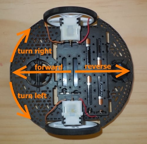
We want the robot to move forward when the direction pin is logic high. To do this, wire the screw terminals to the motor connections as follows:

We have four functions for basic motor movement:
void FullSpeed_Forward(void)
{
	MOT_R_nEN = 1;
	MOT_L_nEN = 1;

	MOT_R_PWM = 1;
	MOT_L_PWM = 1;

	MOT_R_DIR = 1;
	MOT_L_DIR = 1;

	MOT_R_nEN = 0;
	MOT_L_nEN = 0;
}

void FullSpeed_Reverse(void)
{
	MOT_R_nEN = 1;
	MOT_L_nEN = 1;

	MOT_R_PWM = 1;
	MOT_L_PWM = 1;

	MOT_R_DIR = 0;
	MOT_L_DIR = 0;

	MOT_R_nEN = 0;
	MOT_L_nEN = 0;
}

void FullSpeed_TurnRight(void)
{
	MOT_R_nEN = 1;
	MOT_L_nEN = 1;

	MOT_R_PWM = 1;
	MOT_L_PWM = 1;

	MOT_R_DIR = 0;
	MOT_L_DIR = 1;

	MOT_R_nEN = 0;
	MOT_L_nEN = 0;
}

void FullSpeed_TurnLeft(void)
{
	MOT_R_nEN = 1;
	MOT_L_nEN = 1;

	MOT_R_PWM = 1;
	MOT_L_PWM = 1;

	MOT_R_DIR = 1;
	MOT_L_DIR = 0;

	MOT_R_nEN = 0;
	MOT_L_nEN = 0;
}
The general sequence of operations is the same for each function: disable the motors, set the PWM signals to logic high, set the direction according to the movement operation, and then enable the motors. To stop the motors we simply bring the enable pins to logic high:
void StopMotors(void)
{
	MOT_R_nEN = 1;
	MOT_L_nEN = 1;
}
The testing code cycles through the four movement operations then stops the motors before beginning the sequence again:
while (1)
{
	FullSpeed_Forward();
	C2ADAPTER_LEDGRN = !C2ADAPTER_LEDGRN;

	Delay_seconds(7);

	FullSpeed_Reverse();
	C2ADAPTER_LEDGRN = !C2ADAPTER_LEDGRN;

	Delay_seconds(7);

	FullSpeed_TurnLeft();
	C2ADAPTER_LEDGRN = !C2ADAPTER_LEDGRN;

	Delay_seconds(7);

	FullSpeed_TurnRight();
	C2ADAPTER_LEDGRN = !C2ADAPTER_LEDGRN;

	Delay_seconds(7);

	StopMotors();

	Delay_seconds(7);
}
You can download the source and project files via the following link.
RomiRobotControlBoard_source_and_project_files.zip
Summary
In this article, I presented the Romi robot chassis from Pololu and introduced the custom-designed PCB that will control the robot. We powered up the board and connected the motors, then we verified motor-control functionality with some simple testing code. Note that the EFM8 microcontroller was programmed using the C2 adapter board discussed in this article. We’ll explore additional portions of the control PCB in future projects.
Give this project a try for yourself! Get the BOM.