 Facebook
 Google
 GitHub
 Linkedin
Do-It-Yourself Soldering Station with an ATmega8
The mighty soldering iron. If you need one, want one, or just love to build stuff, then this project is for you.
The mighty soldering iron. If you need one, want one, or just love to build stuff, then this project is for you.
What is one of the most essential tools in an electrical engineer’s kit? I’ll tell you one that you probably love and hate; the soldering iron. You don’t have to be an EE to need one, you'll need one even if you're just a tinkerer who enjoys repairing stuff around the house.
For basic applications, a standard soldering iron that you plug into the wall does the job, but for more sensitive work like repairing and building electronic circuits, you'll need a soldering station. The temperature control is critical as to not burn the components, especially the integrated circuits. In addition, you may also need it to be powerful enough to maintain a certain temperature in case you find yourself a big ground plane that you want to solder to.
As a student attending University far from home, I found that it was impractical to uninstall my soldering station from my workbench to bring it back and forth when I visit home. I decided that it was best to get a new one, or better yet, build a new one.
Design
As I designed the soldering station, I had a few key qualities in my mind.
- Portability – This is achieved by using an SMPS (Switched - Mode Power Supply) instead of a regular transformer and rectifier bridge.
- Simple design – I didn’t want any LCDs, unnecessary LEDs, or buttons. I just wanted an LED segment display to show me the set and current temperature. I also wanted a simple knob to select the temperature (potentiometer) and no pot for adjusting the accuracy since it can easily be done by software.
- Universal – I used a standard aviator’s 5 pin plug (some type of DIN) so that it is compatible with Hakko soldering irons and its tips.
The best way to temperature control a soldering iron is, in my opinion, using a microcontroller as a PID (proportional–integral–derivative) controller. It's very likely that you've heard of PID before, for example, 3D printers use it to set the hot end temperature. The principle is not new, as it can be used for anything that requires automatic adjustment and is widely used in the industry. Even your digital thermostat at home uses this type of controller.
How it Works
.png)
First of all, let’s talk about the PID. To explain it bluntly, let’s take our particular case here with the soldering station. The system is constantly monitoring the error, which is the difference between the set point (in our case, the temperature that we want and our current temperature). It adjusts the output of the microcontroller which controls the heater via PWM based on the following formula:
.
As we can see, there are three parameters Kp, Ki, Kd. The Kp parameter is proportional to the error at the present time. The Ki parameter accounts for errors that have accumulated over time. The Kd parameter is a prediction of future error. In our setup, we are using Brett Beauregard’s PID library for adaptive tuning which has two sets of parameters: aggressive and conservative. When the current temperature is far from the set point, the controller uses aggressive parameters, otherwise, it uses the conservative ones. This allows us to have a low heat up time while still achieving precision.
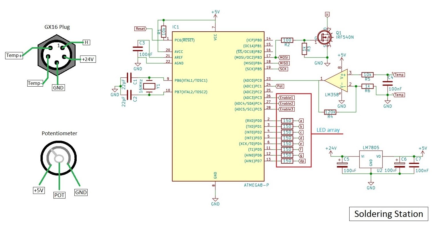
Here is the schematic. It uses an 8-bit microcontroller ATMEGA8 in DIP (you can use an ATMEGA168-328 if you have one of those laying around) which is very common and the 328 variant is found in Arduino UNO. I chose it because it's very simple to program using the Arduino IDE, which also has some good libraries that are ready to go.
The temperature is read by the thermocouple that's built into the soldering iron. We amplify the voltage generated by the thermocouple by about 120 times using an op-amp because of the thermoelectric effect. The output is connected to the ADC0 pin of the microcontroller that turns the voltage into a value between 0 and 1023.
The set point is given by the potentiometer that's used as a voltage divider. It's connected to the ADC1 pin of the ATMEGA8. The range 0-5V (pot output) is changed to 0-1023 by the ADC and again to 0-350 degrees Celsius by the function “map”.
Bill of Materials
| Reference | Value | Count |
|---|---|---|
| IC1 | ATMEGA8-P | 1 |
| U1 | LM358 | 1 |
| Q1 | IRF540N | 1 |
| R4 | 120k | 1 |
| R6;R3 | 1k | 2 |
| R5;R1 | 10k | 2 |
| C3;C4;C7 | 100nF | 3 |
| Y1 | 16MHz | 1 |
| C1;C2 | 22pF | 2 |
| R2 | 100 | 1 |
| U2 | LM7805 | 1 |
| C5;C6 | 100uF (can be lower) | 2 |
| R7;R8;R9;R10;R11;R12;R13;R14 | 150 | 8 |
Here is the bill of materials exported from the Kicad. In addition, you will need:
- Soldering iron Hakko clone, the most popular are on eBay and Chinese websites (with thermocouple, not thermistor)
- 24V 2A power supply (I recommend SMPS, but you can use a transformer with a rectifier bridge)
- 10k potentiometer
- Electrical aviation style plug with 5 pins
- Panel mounted electrical connector
- PCB
- Power switch
- 2.54mm pin headers
- Lots of wires
- Dupont connectors
- Case (I 3D printed mine)
- One triple LED array display
- AVR ISP programmer (you can use your Arduino for this).
Of course, you can easily substitute the LED array with an LCD or use buttons instead of a potentiometer, after all, it’s your soldering station. I stated my design choices, but you can do it however you want it. If you need help with your code or if you are changing components, leave a comment and I will help you!
Build Instructions
First, you have to make the PCB. Use whichever method you prefer, I recommend toner transfer as it’s the easiest way. Also, my PCB is longer because I wanted it to be the size of the SMPS so I can put one on top of the other. Feel free to modify it, you can download the files and edit them with Kicad. After that, solder all the parts to the PCB.
Make sure to put a switch between the power supply and the power connector. Use relatively thick wires for the mains as well as the connection between the power supply and the PCB, as well as between the MOSFET output (H on PCB) and the ground wire for output. To wire the potentiometer, connect the 1st pin to 5V, the 2nd pin to POT, and the 3rd pin to the ground. All of the connections you need are on the PCB. For the LED array, take note that I used a common anode, but yours may be different. You will have to modify the code a bit, but the instructions are commented in the sketch. Connect pins E1-E3 to the common anodes/cathodes and pins a-dp to the corresponding pins on your array. You should consult the datasheet for it. Finally, mount the plug for the soldering station and solder the connections. The picture with the schematic should help you here.
Now comes the fun part, uploading the code. You will need the PID library to do this. If you have an AVR ISP programmer, you know what you need to do. Connect the +5v, Ground and MISO, MOSI, SCK and RESET pins, download the Arduino sketch, open it (you need to have Arduino IDE installed on your computer) and click upload.
If you don’t have one, you can use your Arduino for this. Connect your Arduino (UNO/NANO) to the PC, go to file -> examples -> ArduinoISP and upload that. Then go to tools -> programmer -> Arduino as ISP. Connect as below (PICTURE) and then download the Arduino sketch, open it and click Sketch -> Upload using Programmer.
ATTENTION! If you are using like me, an ATMEGA8 instead of the 168/328 and your Arduino version is greater than 1.6.0 you need to follow these instructions :
That’s it. You can now enjoy your soldering station, built with your own skillful hands.

Calibration
I lied, that’s not it. We need to calibrate it now. Since the heaters and the thermocouples inside have variations, especially if you don’t use an original Hakko soldering iron, we need to calibrate it.
First, you need a digital multimeter with a thermocouple to measure the tip temperature, although the best way to do this is to buy a tip thermometer (eBay has some fake Hakko ones that should be sufficient). After you measured the temperature, you need to adjust the default “510” value in this line in the code : map(Input, 0, 510, 25, 350) using this formula:
where TempRead is the temperature that appears on your digital thermometer and TempSet is the temperature that you have set on your soldering station This is just an approximate adjustment but should be sufficient, you do not need extreme precision for soldering. I used Celsius because this is what it is usually used in electronics, but you can change to Fahrenheit in the code if you would like.
3D Printed Case (optional)
I designed and printed myself a case because I can stack the SMPS and PCB to be nice and tidy. Unfortunately, for you to use this case, you would need to find the exact type of SMPS. If you do have one and want to build it or if you want to modify it to your needs, you can download the files. I printed mine at 20% infill, 0.3 layer height. You can use higher infill and smaller layer height if you have the time and patience.
Conclusion
There are still a lot of things that can be improved, like using a specialized thermocouple IC with cold junction compensation. If you have any suggestions, want any new features, or you just have problems during your build, please leave a comment.
I’ll leave you to thoroughly read the instructions again; find your parts and build the thing. I wish you burn-free soldering!

Give this project a try for yourself! Get the BOM.
Related Content


hi
why do you have 2 versions of the code ?