 Facebook
 Google
 GitHub
 Linkedin
How to Use the Digital I/O on a BeagleBone
Beaglebone Black is the most recent incarnation of the Beaglebone open source hardware platform. For less than $50, the board includes Ethernet, graphics processing, 4Gb of nonvolatile storage, and ports supporting USB, HDMI, and Beaglebone's custom I/O add-ons, called "capes". Here's how to run some simple commands to toggle digital I/O on the board!
Use the general purpose I/O on the Beaglebone Black to get started with this powerful hardware platform!
Recommended Level
Intermediate
Export Only
The simplest way to manipulate the Beaglebone's I/O is through the bash shell. Why? You may have heard that, on Linux, everything is a file. The bash shell provides an easy way to interface with files in a Linux system. Since the Beaglebone Black runs Linux, it's no exception to this rule - even the GPIO on a Beaglebone are files! It just takes a little bit of work to dig down to them. The first step to using our GPIO is to export our chosen pin as a GPIO. That's pretty simple, and involves a simple file write using the 'echo' command:
$ echo 67 > /sys/class/gpio/export
What's the point of this command? Nothing happened to our board! Well, that's not entirely true - it's just not obvious what was going on. The Beaglebone is built around a TI Sitara processor. Like most modern processors, the Sitara family has a ton of pins to interface with the outside world. Conveniently, most of these pins can perform multiple functions. These functions can be extremely simple, like the GPIO function we'll be setting up in a minute, or extremely complex, like a part of a PCIe bus or an SGMII network.
The only tradeoff is that you can't perform all functions of a pin at once. Instead, these pins are multiplexed into a port on the processor's internal bus. That means you have to select what function you want your chosen pin to perform. The `echo` command is writing the number 67 into the file '/sys/class/gpio/export'. That's telling the system that we want to use pin 67 on the board as a GPIO, and that the processor should propagate those settings throughout the system. The precise details of this are pretty complicated, and outside the scope of this article. You'll notice that once you've run your this command, the directory /sys/class/gpio/' has an extra folder:
$ ls /sys/class/gpio

export  gpio67  gpiochip0  gpiochip32  gpiochip64  gpiochip96  unexport
Shifting Directions
When we 'echo'-ed 67 into that file, we told the system to export the settings for GPIO_67. It responded by building the folder 'gpio67'. When we examine the contents of this, we get the following structure:
$ ls -al /sys/class/gpio/gpio67

total 0
drwxr-xr-x 3 root root    0 Jan  1 00:14 .
drwxr-xr-x 7 root root    0 Jan  1 00:00 ..
-rw-r--r-- 1 root root 4096 Jan  1 00:42 active_low
-rw-r--r-- 1 root root 4096 Jan  1 00:14 direction
-rw-r--r-- 1 root root 4096 Jan  1 00:43 edge
drwxr-xr-x 2 root root    0 Jan  1 00:42 power
lrwxrwxrwx 1 root root    0 Jan  1 00:41 subsystem -> ../../../../class/gpio
-rw-r--r-- 1 root root 4096 Jan  1 00:14 uevent
-rw-r--r-- 1 root root 4096 Jan  1 00:20 value
There are two files in the new folder, 'gpio67', of particular interest to us: The first is the `direction` file. If you run the command `$ cat /sys/class/gpio/gpio67/direction`, you should see this output:
$ cat /sys/class/gpio/gpio67/direction

in
If you're familiar with any bare metal embedded processor (i.e. PIC, AVR, HCS08), you'll have heard of a register called the data direction register, and have my permission to skip the rest of this paragraph.
For those of you sticking with us: the data direction register dictates which way data can flow out of a GPIO port. There are only two options - either in, or out. Generally, setting this register up for a certain GPIO pin involves finding the right register, finding the right bit within that register, and writing a nice little 'and' statement in C to set or clear that bit.
Not so for the Beaglebone! When we exported GPIO_67, the Beaglebone created this nice little file to read the processor's data direction register and give it back to us in an easy to read format. Instead of a complex mash of hexadecimal, we get two simple values: 'in' or 'out'. As you may have guessed from the earlier 'cat' command, the default state of this register is 'in' - it can read in data on that pin into the processor, but it can't affect the state of GPIO_67. Let's change that so we can see that pin's output in the real world! We can do that by running another 'echo' command, and using 'cat' to verify that it worked:
$ echo out > /sys/class/gpio/gpio67/direction
$ cat /sys/class/gpio/gpio67/direction
out
Awesome! We've changed this I/O's data direction from an input to an output. Now let's make it do something!
There Is A Light and It Sometimes Goes Out
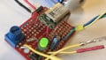
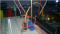
The next step will require you to build a really simple circuit using a single 1-kOhm resistor and your favorite color of LED. You'll need to connect one pin of the LED to pin 2 of header P8 on the Beaglebone, and the other end into any row of a solderless breadboard. Connect one pin of the resistor to the same breadboard row that the LED is plugged into, and the other into GPIO_67 - you can find that on pin 8 of header P.

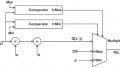
schematic diagram

wiring diagram
Run the following commands, and if everything's tied together properly, you'll see the LED turn on with one, and off with the other.
$ echo 1 > /sys/class/gpio/gpio67/value
$ echo 0 > /sys/class/gpio/gpio67/value
This works on exactly the same principle as the last set of writes to `/sys/class/gpio/gpio67/value` - the only difference between commands is what value gets written into each file. To draw another parallel to more basic embedded systems, the `value` file is comparable to a port data output register. By writing a `1` to it, you're setting the pin to a voltage high of 3.3V. Writing a `0` sets it to a voltage low, and pulls the pin to ground.
Wrapping Up - A Simple Blinking Script
We can chain all of these commands together into a really simple script to toggle the LED on and off every half second:
#!/bin/bash

if [ ! -e /sys/class/gpio/gpio67/value ]
then
    echo 67 > /sys/class/gpio/export
    echo out > /sys/class/gpio/gpio67/direction
fi

while [ True ]
do
    echo 1 > /sys/class/gpio/gpio67/value
    usleep 500000
    echo 0 > /sys/class/gpio/gpio67/value
    usleep 500000
done
This script will run forever - to cancel it, you need to press `Ctrl+c` to get back into a Linux terminal. You can copy it from the excerpt above into your Beaglebone Black, or do a pull from git using this repository.
And there you have it! A simple way to toggle GPIOs on a Beaglebone Black. Who knew it could be so easy?
What have you tied your GPIO to? Made anything cool? Leave us a comment and let us know what you're reading with your Beaglebones!
Give this project a try for yourself! Get the BOM.
Related Content


An example of using the digital input would be helpful