Facebook
 Google
 GitHub
 Linkedin
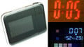
Build a LaunchPad-Controlled Clock with Temperature and Humidity Meter
If you're looking for a cool weekend project, you've found it. This is not only a digital clock: it also measures and displays the temperature and the relative humidity of your room periodically.
Want to learn how to make a Launchpad-controlled clock? We'll do you one better: this is not only a digital clock, it also measures and displays the temperature and the relative humidity of your room periodically. The circuit is built around TI’s LaunchPad and the software is developed in Energia IDE.

Part List
- 1 x LaunchPad Original
- 1 x 4-Digit Seven Segment Display
- 1 x DHT22 Temperature and Humidity Sensor
- 1 x DS1307 Real Time Clock
- 1 x 32.768 kHz Crystal
- 1 x CR2025 3V Battery
- 1 x CR2025 Battery Holder
- 4 x 2N3906 PNP BJT Transistor
- 12 x 100R 1/4W Resistor
- 2 x 2.2 kOhm 1/4W Resistor
- 1 x 100nF Capacitor
- Jumper Wires
- Breadboard
The Circuit

As you can see from the schematic, there are four main components of the circuit: LaunchPad, DS1307 Real Time Clock, DHT22 Sensor and 4-Digit Seven Segment Display.
The DS1307 is a Real Time Clock IC which can provide both time and date information serially over an I2C bus. The transferred data includes hours, minutes, seconds, year, month and day information. The DS1307 requires an external clock with a frequency at 32.768 kHz which can be provided by a crystal oscillator. When the main power of the IC is cut, the IC switches to the backup mode and continues to operate in low current mode.

The time information is directly read from the DS1307 by using the internal I2C module of the LaunchPad. RTCLib library is used for this purpose. The connection between the RTC and the LaunchPad is done over SCL (P1.6) and SDA (P1.7) lines as shown in the schematic. These lines are pulled-up to VCC through 2.2 kohm resistors R2 and R3 for proper I2C operation.
The DS1307 requires 5V supply voltage. Since the LaunchPad doesn’t provide 5V output, an external 5V AC-DC adapter is used. A CR2025 3V Cell is connected to the VBAT pin of the DS1307 as the backup power source which can last a few years.
In our application we don't have external controls to set the date and time of DS1307. To give the current date and time information to the DS1307, we use the following command;
RTC.adjust(DateTime(__DATE__, __TIME__));
This command gets the current date and time of the programmer PC as the input and sets the DS1307 after the sketch is uploaded. It should be commented out after the first upload and used only when a new setting is required.
The temperature and the humidity sensor of the circuit is DHT22, also known as AM2302. DHT22 communicates over a serial single data bus. When the microcontroller sends the start bit, DHT22 transfers a 40-bit data package which includes the relative humidity and the temperature information. In our application we used the DHT22 library adapted to Energia to gather information from DHT22.

Another main component of the circuit is the 4-digit seven segment display. The time, the temperature, and the relative humidity information are shown on the display. Since the segment lines are common for all four digits, the multiplexing method must be used. In this method, we turn on only one digit at a time by using a PNP transistor 2N3906 as a switch. The digits are turned on and off sequentially in 3ms periods. Since this action is fast enough, human eye can not recognize the sequencing and see like all the four digits are on. To limit the LED segment currents, 100 ohm resistors are connected in series.

The Software
The software of the application is built in Energia IDE and it is provided below. The program runs in a loop including the actions below;
- Initialize the board
- Read the time from DS1307
- Display the time for a while
- Read the relative humidity and the temperature data
- Display the temperature for a while
- Display the relative humidity for a while.
The Energia sketch includes comments to clarify each step. Please feel free to ask your questions in the comment section.
#include "Wire.h"
#include "RTClib.h"
#include "DHT22_430.h"
#define DHTPIN P2_6
RTC_DS1307 RTC;
DHT22 mySensor(DHTPIN);

unsigned long timestamp;
unsigned int clockduration = 0;
unsigned int tempduration = 0;
unsigned int humduration = 0;

// Seven Segment Display driver function
void displaydigit (int value, int digit, boolean dot) {

  // Create each digit by turning on and off LED segments
  P1OUT |= 0b00011111;
  P2OUT |= 0b00111000;
  switch (value) {
  case 0:
    P1OUT &= 0b11100100; P2OUT &= 0b11001111; break;
  case 1:
    P1OUT &= 0b11111111; P2OUT &= 0b11001111; break;
  case 2:
    P1OUT &= 0b11100101; P2OUT &= 0b11010111; break;
  case 3:
    P1OUT &= 0b11110101; P2OUT &= 0b11000111; break;
  case 4:
    P1OUT &= 0b11111110; P2OUT &= 0b11000111; break;
  case 5:
    P1OUT &= 0b11110100; P2OUT &= 0b11100111; break;
  case 6:
    P1OUT &= 0b11100100; P2OUT &= 0b11100111; break;
  case 7:
    P1OUT &= 0b11111101; P2OUT &= 0b11001111; break;
  case 8:
    P1OUT &= 0b11100100; P2OUT &= 0b11000111; break;
  case 9:
    P1OUT &= 0b11110100; P2OUT &= 0b11000111; break;
  case 10:
    P1OUT &= 0b11111111; P2OUT &= 0b11111111; break;
  case 11:
    P1OUT &= 0b11111100; P2OUT &= 0b11010111; break;
  case 12:
    P1OUT &= 0b11101100; P2OUT &= 0b11010111; break;
  }

  // Turn on/off the dot LED
  if (dot) P1OUT &= 0b11111011;
  else P1OUT |= 0b00000100;


  // Turn on the selected digit
  digitalWrite(P1_5, HIGH);
  digitalWrite(P2_0, HIGH);
  digitalWrite(P2_1, HIGH);
  digitalWrite(P2_2, HIGH);

  switch (digit) {
  case 1:
    digitalWrite(P1_5, LOW); break;
  case 2:
    digitalWrite(P2_0, LOW); break;
  case 3:
    digitalWrite(P2_1, LOW); break;
  case 4:
    digitalWrite(P2_2, LOW); break;
  }
}

void setup()
{
  // Set the port directions
  P1DIR |= 0b00111111;
  P2DIR |= 0b00111111;


  mySensor.begin();
  Wire.begin();
  RTC.begin();

  // Write the current date and time to DS1397
  RTC.adjust(DateTime(__DATE__, __TIME__));
}

void loop()
{

  // Read and display the time
  while (clockduration <= 500) {

    timestamp = micros();
    DateTime now = RTC.now();
    while (timestamp + 3000 >= micros());

    if (now.hour()/10)
      displaydigit((now.hour()/10),1,0);
    else
      displaydigit(10,1,0);
    delay(3);
    if (now.second()%2)
      displaydigit((now.hour()),2,1);
    else
      displaydigit((now.hour()),2,0);
    delay(3);
    displaydigit((now.minute()/10),3,0);
    delay(3);
    displaydigit((now.minute()),4,0);

    clockduration++;
  }

  displaydigit(10,1,0);
  displaydigit(10,2,0);
  displaydigit(10,3,0);
  displaydigit(10,4,0);

  // Read and display the temperature and the relative humidity
  mySensor.get();
  int32_t h = mySensor.humidityX10();
  int32_t t = mySensor.temperatureX10();


  while (tempduration <= 300) {
    delay(3);
    displaydigit(t/100,1,0);
    delay(3);
    displaydigit((t/10),2,1);
    delay(3);
    displaydigit(t,3,0);
    delay(3);
    displaydigit(11,4,0);
    tempduration++;
  }

  while (humduration <= 300) {
    delay(3);
    displaydigit(h/100,1,0);
    delay(3);
    displaydigit((h/10),2,1);
    delay(3);
    displaydigit(h,3,0);
    delay(3);
    displaydigit(12,4,0);
    humduration++;
  }

  clockduration=0;
  tempduration=0;
  humduration=0;

}
Give this project a try for yourself! Get the BOM.