 Facebook
 Google
 GitHub
 Linkedin
Teardown Tuesday: Projector Alarm Clock with Humidity and Temperature Sensors
In this Teardown Tuesday, we will tear down an LED projector alarm clock with integrated humidity and temperature sensors.
In this Teardown Tuesday, we will tear down an LED projector alarm clock with integrated humidity and temperature sensors.
The Outside
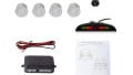
The outside of the LED projector alarm clock shows an LCD display, a rotatable projector, multiple function buttons (on the back), power socket, and a large snooze button on the top. The projector has an adjustable focus dial so that the projected time can be focused correctly depending on the projecting distance.

The LED projector alarm clock
The unit accepts either a 4.5V DC power source (although the provided lead connects to a USB port which delivers 5V) or two AAA batteries. The buttons on the back include mode, up, down, max/min, snooze, and a pinhole reset switch. No other product information can be found on this device, which is unusual considering that most common electronic devices contain some information regarding CE certification.

The back of the LED projector alarm clock
The projection system can swivel around the unit so that the projected time can be pointed to just about anywhere. The projector has a focus rotary dial and can project onto walls as far as 13 feet away.

The projector and focus dial

The projected display from several feet away

The main display when operational
Getting the Unit Open
The alarm clock has no visible screws from the outside but the case shows a line around the perimeter. I tried to pry the two apart but had difficulty, suggesting that screws are used somewhere to prevent separation. After close inspection, I found that the black glassy plastic on the front is only held down with double-sided tape, which was easily removed. This revealed all the screws that keep the unit together.

Case off!
Removing the screws allowed the unit to be separated with ease and revealed the main PCB, multiple switch connectors, wires to battery holders, and the projection unit. Arguably the most interesting feature of this alarm clock is the projector which was the first item to be torn down!

The alarm clock opened
The Projector and Display
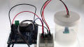
The projector system is very simple yet brilliant! The focusing system is a lens inside a cylinder that allows the lens to move backward and forward. The projection image, itself, is generated with an LCD and a single red LED.
The LCD produces the segmented image and the LED shines through the LCD to produce the 7-segment display. The LCD is only around 1cm in width and uses a flat printed cable to provide connection to the main PCB. Such a 7-segment LCD could be very useful for a DIY project involving a custom HUD or eyepiece with displayed information (only a good bit of probing is needed to reverse-engineer the pinout for the display).

LED projection system

The very tiny LCD display that sits in the square LED backlight projectors
The main PCB is held down with several screws which, when removed, allow it to be disconnected from the main display. Interestingly, the display is not connected to the PCB via a ribbon cable but instead uses a contact pad that relies on the compression from the screws to keep the PCB edge contacts in contact with the display.

The main display removed from the PCB

The compressible contact that connects the PCB and the display together
The Main PCB
The main PCB is a two-layer, FR2-based circuit board with tactile switches, a buzzer, and a power jack on the top side.
From the top side, a crystal (most likely a 32.768 kHz for time keeping) and a sensor can be seen through cut outs in the PCB material. The cut out for the sensor is reasonable as it's likely intended to allow the sensor acess to the evironment. The cut out on the crystal, however, is more strange. This cut out may be intended to prevent the PCB from interfering with the crystal thermally or electrically.

The main PCB

The crystal in its cut-out

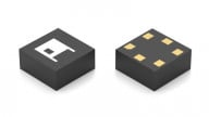
The humidity sensor popping through the PCB cut out
The back of the PCB shows a single chip solution with no ICs (except the main IC under the epoxy), two sensors (temperature and humidity), connectors, diodes, transistors, capacitors, resistors, and LEDs.

The back of the PCB
The LEDs are for providing a backlight for the main display. There's also an LED found inside the LCD projector.
The ribbon cable is for controlling the 7-segment LCD projector, the B+ and B- connectors are for providing power via batteries, and the large edge connector on the top is for connecting the main display to the PCB.

Close-up of the backlight, projector power, and segment control

Main IC, crystal, RH (humidity), and RT (temperature). R stands for relative

Backlight (L- and L+) and battery connector (B- and B+)
Summary
This LCD project clock shows some very interesting components such as a projector which uses a liquid crystal display and LED to cast the digits onto a surface.
The entire product is powered via a single chip solution, which makes sense considering that the use of “chip on board” is far cheaper than using an IC that is housed in a package (when dealing with large quantities).
The PCB, itself, is made of a cheap material which suggests that the intention was to get a decent enough product while keeping part costs as low as possible.


Hello Robin,
Just last night I disassembled this exact model to see if I can use the LCD panel in the projector. Did you by any chance decoded the ribbon cable? If not, I will do so and post it.
Hello.
I want to operate such LCD with an Arduino. is it possible? Is there any published wiring and library for such project ?
Thanks. Dan