 Facebook
 Google
 GitHub
 Linkedin
Make Your Switch Sound Activated
In this article, we'll build a sound-activated switch that can be opened and closed with a double clap.
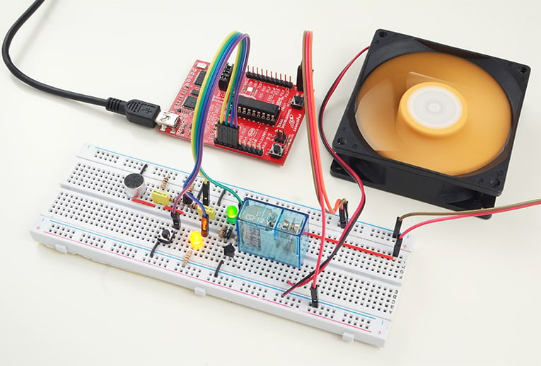
Remember this little bit of magic? We're going to reproduce this device: learn how to make a sound activated switch which can be opened and closed with a double clap. The sound sensing device of the circuit is an electret microphone. The preamplifier circuitry connected to the microphone converts the input coming from the microphone to an analog signal and the internal ADC module of the LaunchPad reads and processes it. When the sound of double clap is detected, a relay is switched on or off over a relay driver circuity. By this way, the power of any gadget connected to the relay can be controlled. For example a fan as you can see in the application.
Part List
- 1 x LaunchPad Original
- 1 x Electret Microphone
- 2 x 2N3904 NPN BJT Transistor
- 1 x SPDT 12V Coil Relay
- 1 x 100R 1/4W Resistor
- 1 x 330R 1/4W Resistor
- 2 x 1K 1/4W Resistor
- 2 x 10K 1/4W Resistor
- 1 x 100K 1/4W Resistor
- 2 x 100nF Capacitor
- 1 x 1N4007 Diode
- 1 x 5mm Green LED
- 1 x 5mm Yellow LED
- 1 x SPST Tact Switch
- Jumper Wires
- Breadboard
The Circuit
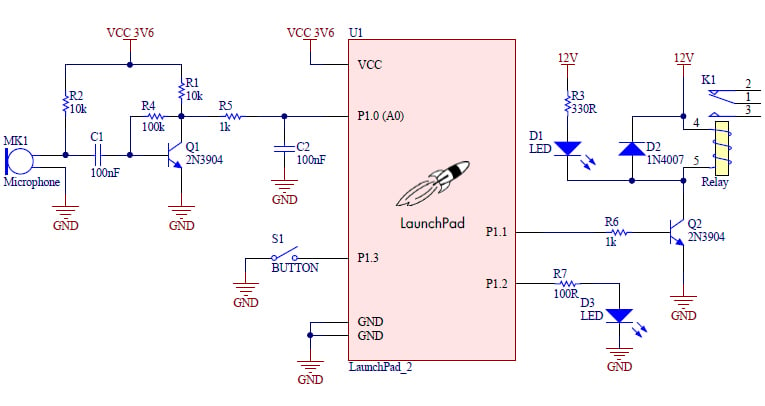
An electret microphone is a type of condenser (capacitor) based microphone that converts sound energy to electrical energy. It is a low cost microphone that can be found in every cellphone, laptop, camera, and so on. The main component of the circuit is the electret microphone and it is used as the sound sensor.
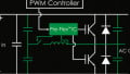
The electret microphone is connected to the preamplifier stage built around the Q1 transistor which amplifies the input signal coming from the microphone. The amplified signal is applied to the A0 analog input of the LaunchPad. We can easily read this analog input and monitor the behavior of the signal during the claps by using the sketch code below.
void setup()
{
Serial.begin(9600);
}

void loop()
{
  int sensorValue = analogRead(A0);
  // print out the value you read:
  Serial.println(sensorValue);
}
On the serial monitor of the Energia IDE, we can get the readings and create a graph in Excel. Here you can see what the audio signal looks like during the clap test:
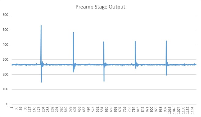
You can see that the DC offset of the audio signal is about 260 units. The peaks generated by the claps can go up to 500 units. The main purpose of the LaunchPad code is detect these peaks and activate the relay when a double clap is sensed.

Actually, sensing any double clap is not enough for the desired clap operation. The interval between the two claps is also important. A timeout procedure is applied in the code and a clap is discarded if it is not followed by another clap in 500ms.
A tact switch is used to adjust the threshold level of the clap action that will be detected. There are three different threshold levels and the yellow LED brightness changes depending on the selected level. The LED gets brighter when the sensitivity gets higher.
When the software detects the double clap, it toggles the P1.1 output which drives a green LED and a relay through a relay driver. The green LED indicates the output status. The relay driver circuit based on the Q2 transistor is required since the output pin current rating of the LaunchPad is limited to 6mA and not capable to drive the relay coil. A 1N4007 diode is placed between the coil terminals to prevent the back EMF.

The Software
The software of the application is built in Energia IDE and it is provided below. The Energia sketch includes comments to clarify each step.
As you can see in the video, the circuit doesn't respond to a single clap and toggles its output when only a double clap is sensed.
unsigned long int timestamp;
int sensitivity=350;


void setup()
{
  // Set the pin modes
  pinMode(P1_1, OUTPUT);
  pinMode(P1_2, OUTPUT);
  pinMode(P1_3, INPUT_PULLUP);
  digitalWrite(P1_1, LOW);
  analogWrite(P1_2, 150);
}

void loop()
{
  // Detect the first clap sound
  if (analogRead(A0) > sensitivity) {

    delay(100);
    timestamp = millis();

    do {
      // Detect the second clap sound
      if (analogRead(A0) > sensitivity) {
        digitalWrite(P1_1, !digitalRead(P1_1));
        delay(100);
        break; // Second clap is detected, break the while loop
      }

    }

    //Discard the first clap if the second clap is not received in 500ms
    while(millis() < (timestamp + 500));

  }

  // If the sensitivity buton is pressed, change the sensitivity level
  if (!digitalRead(P1_3)) {

    if (sensitivity == 400) {
      sensitivity = 350;
      analogWrite(P1_2, 150);
    }
    else if (sensitivity == 350) {
      sensitivity = 300;
      analogWrite(P1_2, 250);
    }
    else if (sensitivity == 300) {
      sensitivity = 400;
      analogWrite(P1_2, 50);
    }
    delay(500);
  }
}
Give this project a try for yourself! Get the BOM.
Related Content


The preamplifier Q1 is a CE amplifier and so I was expecting to see the graph inverted! I.E. When there is no clap, the Q1 output through R5 is high and applied to P1.0. When a clap happens, the transistor turns on taking the P1.0 input low.
What am I missing here?
Hello
I want to try this one but I’ve never done anything like it before - no electronic /circuits experience. can someone tell me what the specs for the fan are?
What limits the load that can be used?