 Facebook
 Google
 GitHub
 Linkedin
Teardown Tuesday: Sound-Activated LED Party Lighting
See what's inside a sound-activated LED for use in DJ environments.
In this Teardown Tuesday, we will be looking at the internals of a sound-activated LED for use in DJ environments.
Party All Night!
This sound-activated light is designed to change its LEDs' color and orientation based on sounds picked up by an internal microphone. The result is a light that reacts to the sounds around it, keeping up with, say, the bass beats of a DJ's set.
The device comes in a plastic packaging and is powered by mains electricity. The top of the dome is made of plastic with many bumps to help spread the light emitted in different directions and the built-in stand helps to keep the unit upright.

The disco light in all its glory

Top of the DJ Light
The label on the bottom of the unit shows that the power consumption ranges between 3W and 12W. It also shows company information.
The bottom also has small vents which may be included for heat dissipation (remember, heat rises and therefore a vent at the top helps to draw cooler air in towards the bottom). However, considering how this unit is sound-activated, those “vents” may just be styled holes to allow sound waves inside to where the microphone is located.
The base of the unit is held in with four screws which is strange considering how this is a mains-powered unit. Many mains-powered devices use a molded design to minimize the chance of electric shock.

The label and “vent” holes

One of the four screws that keep the unit together
Taking a Look Inside
Removing the screws brings out the bottom plastic disc that holds all the major parts including the motor drive, LEDs, and main controller board.
Strangely, the mains cable to the PCB connects via a simple connector (the connector may not be rated for such voltages). However, the middle pin in the three-way connector is missing which helps to provide adequate separation between the line and neutral conductors. (Yep, you read that correctly—it’s called line and not live because neutral is also live.)

The top removed
When the unit operates, the LED PCB moves back and forth to give the effect of moving lights when music plays. The PCB cannot be fully rotated due to the four cables that provide the power to the LEDs and so, instead of full rotation, the PCB moves back and forth.
Below the LED PCB is the gearbox that is responsible for the swaying motion which is most likely controlled via a microcontroller.

The motor and mounted gearbox
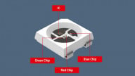
The LED PCB is rather simple with three LEDs mounted (all with dome lenses), four cables, and a single screw hole in the middle. On the PCB, itself, are three exposed copper circles which may be fiducial markings for a pick-and-place machine. Having said that, considering the side of the LEDs, it is also likely that these were soldered by hand.

The LED PCB

If you look real hard into the lenses, you can see the two studio lights used during the teardown

The main PCB fixed to the base
The Main PCB
Top Side
The main PCB is made from an inexpensive material (most likely FR-2, which is also known as synthetic resin bonded paper).
The top side of the PCB consists of several through-hole parts including a transformer, capacitors, connectors, and an electret microphone. For some reason, there are many holes in the PCB which do not seem to relate to pads or potential components. Their function is completely unknown and I personally have never seen anything like it.

The main PCB
Bottom Side
The underside of the PCB reveals many surface-mount parts and a few IC packages.
The power handling section of the PCB and the driver circuit are kept completely separate from each other with the transformer providing the isolation.
The power section shows a rectifier and an IC whose purpose must involve bringing the voltage down. My evidence to support this comes from the fact that there is a 400V capacitor near the rectifier but the capacitor that connects to the IC is rated at only 50V.
One cool feature is the squiggly line on the line conductor which cannot be for timing requirements (commonly found on high-speed digital traces) and so must have to do with current limiting or, as a last resort, a fuse. If the current surge becomes too great and the fuse in the plug fails, this trace will heat up and break.

The power handling side

Squiggly line!
The left side consists of many surface-mount parts that handle the lights and motor.
The IC shown here is unmarked (just like the IC on the power side) and therefore makes it next to impossible to identify. However, two giveaways can be spotted that tell us that this is a microcontroller. Firstly, the system creates fancy patterns when it detects sound and I highly doubt that there is an IC manufacturer who creates disco DJ ICs. Secondly, the IC sits on a space intended for a different chip. Many ICs (such as the PIC range from Microchip), can be interchanged with smaller parts without requiring a redesign of the PCB. For example, master clear on many PICs is on pin 1.

Unmarked controller

Other surface-mount parts on the controller side
Summary
This DJ sound-activated controller shows a mixture of through-hole construction and surface-mount parts. The lack of IC markings is indicative of an intention to keep designs secret and an attempt to keep the production costs as low as possible.
The PCB, however, does show some interesting design choices, including the use of a small trace on the line conductor and the many random holes that do not seem to do anything.
Just for fun, there is a great slogan found on the box!

Enjoy your life!
Next Teardown: Baofeng Amateur Radio Transceiver


Any idea what voltage is produced by the power supply? I’d like to power these via battery.
Hey, this might be a simple question but I would like to know the input voltage given to the LED board? Thanks in advance.