 Facebook
 Google
 GitHub
 Linkedin
Teardown Tuesday: Kwikset SmartCode Lock
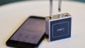
In this Teardown Tuesday, we will take a look at the Kwikset SmartCode Lock.
Want to know what's inside a Kwikset SmartCode lock?
The Kwikset Smart Code deadbolt lock is a residential lock with an integrated motor and keypad so a pin code can be used in placed of the key. In this week’s teardown Tuesday, we will take a look at what makes this lock work.
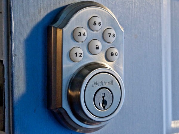
Kwikset SmartCode deadbolt Lock mounted to a door
This article will look at the electronics in the lock; the mechanical aspects of the lock are pretty neat as well. For more information on the unique mechanics of the Kwikset SmartKey Lock used in this deadbolt, take a look here.
Keypad
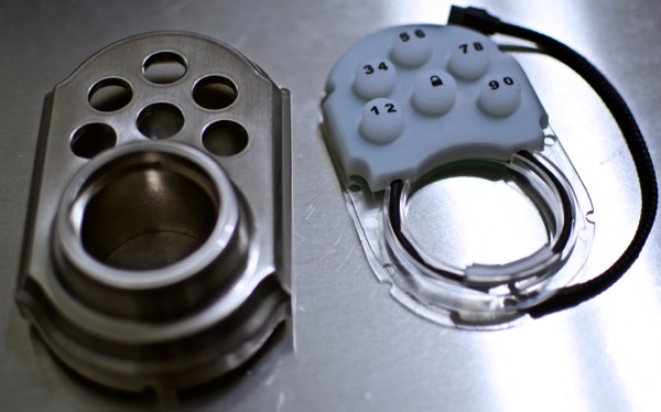
Components of the front keypad assembly
The first component of the deadbolt we'll look at is the keypad. The keypad is comprised of a cast zinc body, a rubber keypad, and a PCB. The keypad PCB is fairly unpopulated; the only components that are on the circuit board are 4 SMD LEDs and 6 dome switches.

Keypad PCB with LEDs and dome switches
On the back of the circuit, two wiring harness are soldered in place. These terminate in a 14 pin keyed connector.
.jpg)
The wiring harness that connects the keypad to the other electronics
Motor Driver
The motorized deadbolt is powered by a 130 size DC motor. The motor is controlled by a motor driver comprised of 6 discrete transistors.
.jpg)
The motor driver comprised of 6 transistors and several resistors
The motor, which is attached to the gearing mechanism, gets plugged into the Metal contacts (MJ1 and MJ2).
.jpg)
The 130 sized motor that is attached to the gearbox, notice the slots for the metal contacts
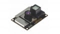
Optical Encoder
.jpg)
The reflective disk mounted to the gearbox that is used to determine the position of the locking bolt
In order to determine the position of the bolt, the system uses a reflective wheel and an optical sensor. The optical sensor used is the EE-SY193 by Omron
.jpg)
The small Omron IR optical sensor
Microcontroller
It's difficult to tell from the images due to the conformal coating, but the SmartCode Lock is controlled by a TI MSP430F5324 microcontroller. This is a 64 pin, 16-bit, microcontroller designed for low power applications.
.jpg)
The TI MSP430 microcontroller in a 64 pin exposed pad package
Expansion Slot
.jpg)
The Z-Wave expansion slot
Kwikset uses these same electronics in a variant of the SmartCode Lock that included a Z-Wave wireless modem for smart home integration. There is a right-angle female header pin at the top of the device that the modem plugs into.
Other Miscellaneous Components
Kwikset is also using a self-resetting poly fuse on this board that is attached directly to the positive terminal of the battery connector
.jpg)
The self-resetting Polyfuse inside the lock
A CTS 209-4MS 4 position dip switch is used to allow the user to input various settings.
.jpg)
The 4 position settings dip switch
Conformal coating is used in select areas of the circuit board to increase the moisture resistance of the electronics.
.jpg)
The conformal coating around an LED
Moving Forward
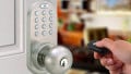
Due to the Z-Wave connector, some people are adding their own custom electronics to this lock. Here is an example of someone Controlling the Kwikset SmartCode Lock with an Intel Edison.
With electronic locks becoming more and more common, it will be likely to see many more hacks, projects, and other information on similar products in the near future.
Next Teardown: Amazon Dash Button


Nice work! And thanks for the link to my instructable. I wanted to point out a detail that you missed (probably since you didn’t disassemble the gearbox). The board also has absolute position encoders in the form of 3 hall effect sensors that look like ordinary transistors in their SOT23 packages on the board. The arm inside the plastic gearbox has a couple of magnets that let the lock know when it’s gotten to fully unlocked or locked for both right hand and left handed door installation.