 Facebook
 Google
 GitHub
 Linkedin
Teardown Tuesday: Keyless Entry Door Lock
In this teardown, we unlock an electronic touchpad keyless entry door lock system to learn some of its secrets.
In this teardown, we unlock an electronic touchpad keyless entry door lock system to learn some of its secrets.
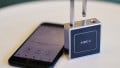
Smart locks are a popular addition to many modern homes. Some locks can be controlled with Bluetooth connectivity, some with keypads, some with remote controls, and some with all three.
Today we'll rip into a smart lock with a keypad and the option for an app.
A Robust and Smart Door Lock
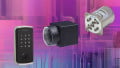
Although this electronic touchpad keyless entry door lock from MiLocks arrived in a plain shipping box, it includes everything needed—except for the installation tools—for adding this lock to your door.

MiLocks apparently saves money by not adding glamour to their plain shipping boxes, which is perfectly acceptable if you ask me.

Except for installation tools, MiLocks provides everything that's needed, including batteries.
The Door Lock Keypad
The electronics contained inside the external door lock are rather simple; all that's included is a keypad with some LEDs and a cable. The door lock, itself, the metal plate, and the metal enclosures are all impressively sturdy, but one should expect no less given their purpose in life.
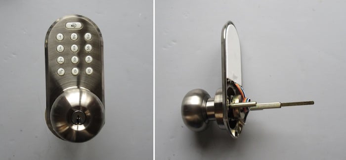
The door lock piece that is external to the house is impressively sturdy and contains minimal electronics.
Removing the keypad from the door lock was quite simple. Only a few strips of double-sided tape secures the keypad in place.
_resize.jpg)
No screws used here. The keypad is attached to the door lock by use of double-sided tape.
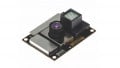
Separating the membrane keypad from the PCB (and its pushbuttons) was a matter of merely unpeeling the keypad from the PCB. The figure below shows the thirteen pushbuttons. The eight LEDs have also been called out.
.jpg)
The unsoldered snap dome switches are held in place by the membrane keypad. Click to enlarge.
The pushbuttons, by the way, are not soldered to the PCB but are simply held in place by the membrane keypad, itself.This is the normal design approach when using such snap doom tactile switches, like these (PDF).
The Door Lock Assembly that Contains the Brains
The remaining electronics—including the "brains" of this smart door lock—reside inside the in-the-house portion of this door lock assembly. The four AA batteries are easily accessible by sliding the battery cover out of the way. Also located underneath the battery cover are the controls (pushbuttons and switches) for programming the door lock.

The batteries and programming switches are located underneath the battery cover.
The electronics of this door lock are easy to get to once the metal plate and associated three screws are removed (see figure below).
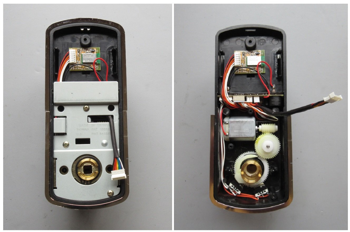
Accessing the electronics was surprisingly simple with the removal of the metal plate and its three screws.
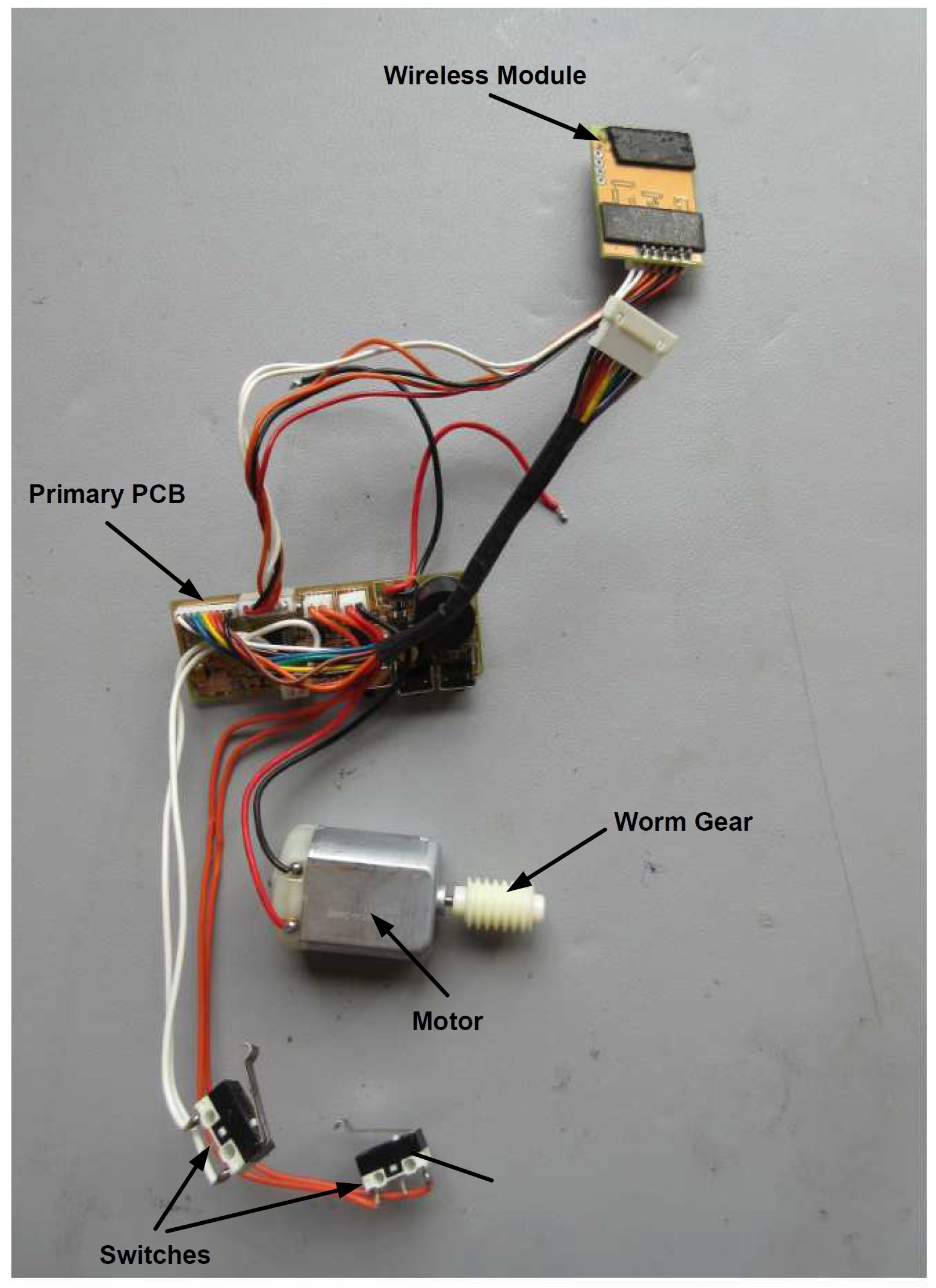
With the metal plate removed, we can see the gears, the DC motor, wires, switches, and of course the PCBs. And with all the electronics removed from the door lock enclosure, we can see how simple of a design this electronic touchpad entry system really is.
The simple design approach is noticeable once the electronics are removed from the door lock enclosure. Click to enlarge.
Examining the Electronics
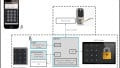
The smarts of this electronic touchpad keyless entry system consists of only two PCBs, one of which includes the Bluetooth circuitry that uses an apparent OTS (off the shelf) module. The other PCB provides a home for the brains (the microcontroller), the FETs (which are used for dictating the direction of the current flow and, thus, the direction of the motor), and the buzzer.
Both PCBs are two-layer designs (no internal layers), which is always helpful for keeping production costs down.
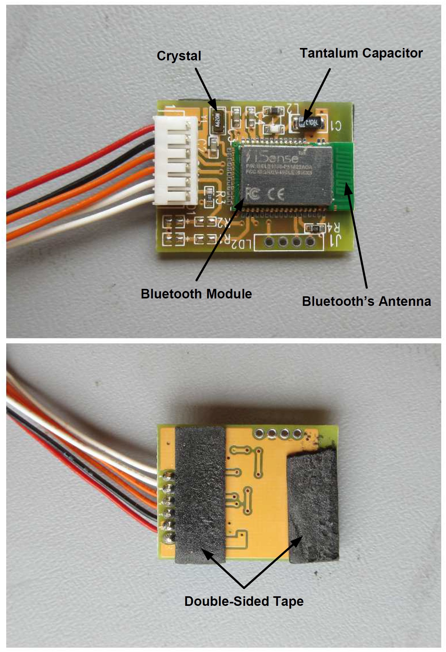
The wireless communications PCB uses an off-the-shelf Bluetooth module. Click to enlarge.
- Crystal: Part marking A620N (no datasheet could be located)
- Tantalum capacitor: Part marking C106L
- Bluetooth module: iSense ISBLE1810-P51822ACA

The primary PCB includes all the other electronics. Click to enlarge.
- Microcontroller: Part marking PIC16LF1938
- Voltage regulator: Part marking EAK6A (no datasheet could be located)
- Buzzer: Part marking OBO-1205A-D2
- Pushbuttons: Part marking GP L43
- MOSFETs: Part marking C3021LD
- Motor (shown in previous figure): Part marking FC-280SA-2865
Conclusion
This teardown has shown us the rather simple electronics design approach that MiLocks has implemented in their electronic touchpad keyless entry door lock system. Part of this simple design is made possible by leveraging the seemingly ready-to-go Bluetooth module. So kudos to MiLocks for using OTS parts in place of designing, from scratch, complicated subsystems!
Featured image used courtesy of MiLocks.
Next teardown: Smart Doorbell and Camera System


I would be concerned about how secure it really is. I’ve heard of lots of devices being broken into using SDR devices to determine the codes. Then again the likelihood of someone going through that trouble is low.
I’ve used N° entry door locks at work, but 1s that don’t use electric, so how can they work? must = energy from pressing keys.
Connector pins 17 and 18 for 32.768KHz crystal