Facebook
 Google
 GitHub
 Linkedin
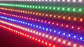
Make an Analog Sound Reactive LED Strip
This analog design allows your LEDs to respond to your music. Just plug your music source into this which sends a channel to your sound system and some LEDs.
Make LEDs that react to your audio input-- great for weddings and bar mitzvahs!
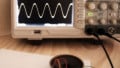
This project will connect an LED strip to an analog circuit (as opposed to using Arduino or a microcontroller, though it does use a linear amplifier IC) that has a music source as an input (the ever-so-popular 3.5mm audio cable). It's pretty cool to have at parties and also works well for action movies, if using the low pass RC filter.
Parts Needed
- RGB strip 5050 model
- 12V power source
- 4 SPST switches (any will do)
- LM158J amplifier
- IRFU3711ZPBF MOSFET
- L7805CV Voltage Regulator
- Capacitors (1 x 0.33uF, 1 x 0.1uF, 2 x 330uF*)
- Resistors (1 x 10 ohm, 2 x 100 ohm, 1 x 220 ohm*, 1 x 47 kohm*)
- 3.5 mm audio jack
- wiring
- Breadboard (optional)
- 100k pot (optional)
- PCB board for final
- Audio cable split (depends on your setup)
- RGB 5050 connector
As with most projects, I suggest building this on a breadboard to make sure everything works how you would like it to. I built this circuit to react to the low frequency tones of the music vs. the high frequency, and you can adjust values (more on that in the input filter section) to your liking. Please use caution when handling electricity (it's only 12V, but I wouldn't stick it on my tongue). This project also assumes you own a soldering iron and know how to solder.
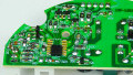
Electrical Diagram/Sectioned Diagram

Input Filter
The input filter stage of this circuit is mostly the part of the circuit that you would want to make your own. As you can see in my diagram, this portion is just a simple RC circuit. You can adjust the resistor and capacitor values as you see fit. The RC circuit filter allows for only the passing of low frequencies. If you want to pass high frequencies only, I would suggest using an RL circuit. You can build these circuits in multiple stages, but you will also need to adjust the linear amplifier for the filter with more loss. I use a simple 1-stage filter, as it gives me the desired results.
The formula for finding the cutoff frequency is:
$$f = \frac{1}{(2*pi*RC)}$$
Here I use two 330 uF capacitors in series to give an equivalent capacitance of 165 uF with a 100 ohm resistor. The cutoff frequency here would be 10 Hz. I use such a low cutoff because this is one stage, so the cutoff is not absolute but rather biased towards that frequency. Using a mutli-stage filter would give a sharper curve (resembling a square wave), but it would not be neccessary in this application. Also, higher resistance is always good for audio inputs in my experience. I connected the input using one of the 3.5 mm ports (see picture for "pins"); the polarity of the music will not matter.

Linear Amplifier
The linear amplifier will incorporate the LM158J and the L7805CV regulator (it drops the voltage from 12V to 5V for the VCC of the chip) . You may be able to just tie it directly to the 12V source, but I like to use the good ole' 5V for IC chips. I would just build the regulator portion as shown with the correct capacitors for a better 5V signal. This also isolates from the erratic current spikes from the LED strip turning on.
The linear amplifier is also a very straightforward approach; this part was copied off the datasheet. Though R2 and R1 determine the signal gain, I use 47 kohm for R2 and 220 ohm for R1. The formula is as follows:
$$G = 1 + \frac{R2}{R1}$$
So with my values, I have a gain of 236. Should be enough, if not overkill.
Here if you want to include a gain adjuster for different sources, I would change R2 for the 100 kohm potentiometer. The signal resistor serves the purpose of having a path to ground when there is no signal (it discharges any stray capacitance in the chip).
Note: Since the audio source will probably have an audio adjuster that can be considered a pre-amp, it can also be used as a primitive gain adjuster, negating the need for the potentiometer, hence why it's listed as optional.
Electrical Switching of LEDs and Power Source
This portion is also straightforward: the MOSFET, in concept, "shorts" the D and S pins whenever proper voltage has been applied across G and S. I use the IRFU3711ZPBF MOSFET because of its price mainly, but it has all the correct ratings for this application. R5 serves as a "0" signal to the MOSFET when there is no voltage being applied.
The 12V power source amperage should be sized so that its amperage can sufficiently turn on all LEDs connected.
Once everything is constructed, you should connect your music source to the audio cable split, and then one will go into the circuit and the other will connect to your sound system. See picture. Also worth mentioning is that the volume of the sound system playing the music will not affect the sensitivity of the LEDs, but the volume of the sound source will.

Give this project a try for yourself! Get the BOM.
Related Content