Facebook
 Google
 GitHub
 Linkedin
EFM8 Sound Synthesizer: Driving the Speaker
Part 2 in the “How to Make an EFM8-Based Sound Synthesizer” series.
Introduction
Part 2 in the “How to Make an EFM8-Based Sound Synthesizer” series.
Recommended Level
Intermediate
Required Hardware/Software
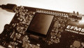
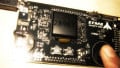
- SLSTK2000A EFM8 evaluation board
- Simplicity Studio integrated development environment
- Components listed in BOM
| Description | Quantity | Digi-Key p/n |
| Breadboard | 1 | 377-2094-ND |
| Receptacle-to-plug jumper wires | 4 | 1471-1231-ND |
| 5 V AC/DC wall-mount power supply | 1 | 1470-2771-ND |
| 0.1 µF capacitors | 4 | 399-4266-ND |
| Fifth-order switched-capacitor lowpass filter | 1 | LTC1063CN8#PBF-ND |
| General purpose op-amp | 2 | LT1638CN8#PBF-ND |
| Analog power buffer | 1 | LT1010CN8#PBF-ND |
| 2 µF capacitors | 2 | 490-8835-ND |
| 10 kΩ resistors | 2 | 10KQBK-ND |
| 100 Ω resistor | 1 | 100QBK-ND |
| 8 Ω, 1 Watt speaker | 1 | GF0771-ND |
Project Overview
In the previous article, we successfully generated a sine wave by passing a square wave through a fifth-order switched-capacitor lowpass filter. We were also able to vary the frequency of this sine wave by adjusting the frequency of the square wave as well as the frequency of the clock signal that determines the filter’s cutoff frequency. Our goal now is to use this sine wave to drive a speaker, but before we do that we need to address three undesirable qualities in the signal available at the filter’s output pin:
- It contains high-frequency noise referred to as “clock feedthrough.”
- It has a nonzero DC offset.
- It cannot drive a speaker because the LTC1063 cannot supply sufficient output current.
In this article we will focus on redressing these three deficiencies with some simple signal-conditioning circuitry, and then we will modify the firmware so that the speaker plays a sequence of sounds corresponding to the C major scale.
Here is the entire schematic for this project:

In the following sections, relevant portions of the schematic will be reproduced in magnified form.
Clock Feedthrough
Switched-capacitor filters offer significant advantages over standard passive or active filters, but there is always a trade-off. A prominent downside with switched-cap technology is clock feedthrough. In the LTC1063, the digital clock signal is directly controlling the circuit that filters the analog signal. Thus, it is not surprising to find that our sine wave exits the chip having acquired some high-frequency noise. Here is the LTC1063 output for a 523.25 Hz signal (corresponding to musical note C5):

A closer look reveals the clock feedthrough noise:

The cursors confirm that the noise is caused by the clock, because the clock frequency is 523.25 Hz × 125 = 65.4 kHz (recall from the previous article that the clock-signal-to-sound-signal ratio is 125 to 1). You can see that the noise resembles the “stair-step” pattern that occurs in the analog signal from a digital-to-analog converter or in the binary numbers generated by an analog-to-digital converter. This reminds us that a switched-cap filter is actually sampling the input signal, like an ADC, and we are using “clock feedthrough” to denote the stair-step clock noise that is present in the output of any sampled-data system. It is advantageous for IC manufacturers to design switched-capacitor filters such that the clock-to-cutoff ratio is high, because then the clock feedthrough noise can be effectively suppressed with a simple first-order RC lowpass filter:

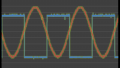
R1 and C3 provide 20 dB/decade roll-off with a cutoff frequency of 1/(2πRC) = 796 Hz. This means that the clock frequency shown above will be attenuated by almost 40 dB, which is a factor-of-100 reduction in amplitude. All other clock frequencies will be attenuated even more because note C5 is the lowest note in the scale used for this project, which starts with C5 (523.25 Hz) and ends with C6 (1046.5 Hz). The following scope trace, measured at pin 3 of the op-amp component, demonstrates the efficacy of the filter:

You may be wondering why the cutoff frequency is set at 796 Hz if we are using audio frequencies as high as 1046.5 Hz. That’s a good question, and the video at the end of this article clearly shows that the higher notes in the scale are being attenuated by this lowpass filter. You may also notice, though, that the higher notes do not sound less loud than the lower notes. Actually, they sound a little louder. This occurs because both our speaker and our sense of hearing favor the higher frequencies. The human ear exhibits gradually increasing responsivity from C5 (about 500 Hz) to C6 (about 1 kHz), and the speaker’s frequency response also shows an overall increasing trend in this band:

So, placing the cutoff frequency near the middle of our frequency range actually helps to balance the perceived loudness of the notes in the scale.
DC Offset
The average value of the sine wave that we send to the speaker should be zero—in other words, pure AC with no DC component. A DC offset in an audio signal biases the speaker’s voice coil and thus reduces dynamic range, and it can also contribute to distortion. In our circuit we remove the DC offset simply by inserting a DC-blocking capacitor (C6) between the output of the first op-amp and the input of the second.

At this point in the circuit we also use R3 and R4 to reduce the signal amplitude by half; we do this because a full-amplitude signal would require more current than our buffer can reliably supply, as discussed in the next section.
Power Amplifier
The note C5 audio signal at the output of the second op-amp looks like this:

The peak amplitude is 1.32 V. If we tried to drive our 8 Ω speaker with this signal, the peak current would be approximately 1.32 V / 8 Ω = 165 mA. The maximum output current of the LT1638 op-amp, however, is in the range of 25 mA. This is why we need a power amplifier stage—the voltage amplitude is fine, but we need something that can supply more current and thereby deliver a meaningful amount of power to the speaker. For this we use the LT1010, which is a unity-gain buffer that can increase the output current capacity of an existing op-amp circuit to about 150 mA:

As indicated by the schematic, the LT1010 is designed to be included within the feedback loop of the op-amp. The speaker’s positive terminal is connected to the LT1010’s output pin, and the negative terminal is connected to the circuit’s ground node. Here is the signal that drives the speaker:

Why is the peak amplitude only 800 mV instead of 1.32 V? Because the voltage shown here is essentially the output of a resistive voltage divider composed of the LT1010’s output impedance and the speaker’s 8 Ω coil impedance. The LT1010’s output impedance is specified at somewhere between 5 and 10 Ω; in this case it appears to be about 5 Ω, because Vspeaker = 800 mV ≈ 1.32 V × (8 Ω / (8 Ω + 5 Ω)).
With a peak amplitude of 800 mV, the LT1010 must supply 800 mV / 8 Ω = 100 mA, which is comfortably within its maximum current rating. Now you see why we reduced the voltage by half at the input to the second op-amp: a peak amplitude of 1.6 V applied to the speaker would require 200 mA. The LT1010 could probably endure this because we are operating at moderate temperatures and because our sinusoidal current is not constantly at 200 mA, but the world is stressful enough as it is—why stress out the LT1010 just for a demo project?
Firmware
The firmware for this project is the same in terms of port I/O, peripherals, and interrupts. The new code is related to the new sound frequencies we are generating:
#define SOUND_C5_INCREMENT 1958
#define FILTCLK_C5_INCREMENT 16
#define SOUND_D5_INCREMENT 1744
#define FILTCLK_D5_INCREMENT 14
#define SOUND_E5_INCREMENT 1554
#define FILTCLK_E5_INCREMENT 12
#define SOUND_F5_INCREMENT 1467
#define FILTCLK_F5_INCREMENT 12
#define SOUND_G5_INCREMENT 1307
#define FILTCLK_G5_INCREMENT 10
#define SOUND_A5_INCREMENT 1164
#define FILTCLK_A5_INCREMENT 9
#define SOUND_B5_INCREMENT 1037
#define FILTCLK_B5_INCREMENT 8
#define SOUND_C6_INCREMENT 979
#define FILTCLK_C6_INCREMENT 8
Now we have sound-signal and clock-signal increments for all the musical notes (excluding sharps and flats) from C5 to C6. The main while loop repeatedly plays the C major scale by cycling through the appropriate increment values, with each note being held for one second:
while(1)
{
	Current_SoundSignal_Increment = SOUND_C5_INCREMENT;
	Current_FilterClock_Increment = FILTCLK_C5_INCREMENT;

	//delay 1 second
	SFRPAGE = TIMER3_PAGE; TMR3 = 0; while(TMR3<10000);

	Current_SoundSignal_Increment = SOUND_D5_INCREMENT;
	Current_FilterClock_Increment = FILTCLK_D5_INCREMENT;

	//delay 1 second
	SFRPAGE = TIMER3_PAGE; TMR3 = 0; while(TMR3<10000);

	Current_SoundSignal_Increment = SOUND_E5_INCREMENT;
	Current_FilterClock_Increment = FILTCLK_E5_INCREMENT;

	//delay 1 second
	SFRPAGE = TIMER3_PAGE; TMR3 = 0; while(TMR3<10000);

	Current_SoundSignal_Increment = SOUND_F5_INCREMENT;
	Current_FilterClock_Increment = FILTCLK_F5_INCREMENT;

	//delay 1 second
	SFRPAGE = TIMER3_PAGE; TMR3 = 0; while(TMR3<10000);

	Current_SoundSignal_Increment = SOUND_G5_INCREMENT;
	Current_FilterClock_Increment = FILTCLK_G5_INCREMENT;

	//delay 1 second
	SFRPAGE = TIMER3_PAGE; TMR3 = 0; while(TMR3<10000);

	Current_SoundSignal_Increment = SOUND_A5_INCREMENT;
	Current_FilterClock_Increment = FILTCLK_A5_INCREMENT;

	//delay 1 second
	SFRPAGE = TIMER3_PAGE; TMR3 = 0; while(TMR3<10000);

	Current_SoundSignal_Increment = SOUND_B5_INCREMENT;
	Current_FilterClock_Increment = FILTCLK_B5_INCREMENT;

	//delay 1 second
	SFRPAGE = TIMER3_PAGE; TMR3 = 0; while(TMR3<10000);

	Current_SoundSignal_Increment = SOUND_C6_INCREMENT;
	Current_FilterClock_Increment = FILTCLK_C6_INCREMENT;

	//delay 1 second
	SFRPAGE = TIMER3_PAGE; TMR3 = 0; while(TMR3<10000);
}
In the next article we will expand the firmware to incorporate USB connectivity and additional timing functionality so that we can conveniently synthesize melodies.
Video
Refer to the “Clock Feedthrough” section for an explanation of why the amplitude decreases as the frequency increases. The static you hear is due to the recording process; the sound coming out of the speaker is clean and pleasant, especially the lower notes.
Next Article in Series: EFM8 Sound Synthesizer: Playing Melodies via USB
Give this project a try for yourself! Get the BOM.
Related Content