 Facebook
 Google
 GitHub
 Linkedin
Measuring Temperature with an NTC Thermistor
For this article, we are only concerned with one type of sensor that can measure temperature. This sensor is called a thermistor.
Learn about thermistors and how to program an Arduino to measure its data.
Have you ever wondered how some devices like thermostats, 3D printer heat beds, car engines, or ovens measure temperature? With this project, you can find out!
Knowing the temperature in a project can a very useful piece of data to have handy. Knowledge of temperature can help regulate room temperature for a comfortable environment, ensure that a 3D printer bed is hot enough for materials like ABS to stick to its surface, prevent engine overheating, and keep food from being burnt.
For this article, we are only concerned with one type of sensor that can measure temperature. This sensor is called a thermistor.
A thermistor exhibits resistance that is far more sensitive to temperature than that of other types of resistors.
We will use an Arduino to measure and process the reading from a thermistor and then convert this into a human-friendly format of common temperature units.
Below is a picture of the thermistor we are going to use:
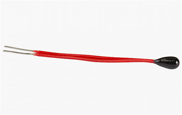
A bead thermistor. Image courtesy of Thorlabs.
BOM
Hardware
- Arduino
- MEGA or Uno or your favorite flavor of Arduino
- Some jumper wires
- Solder and soldering iron (maybe in case your thermistor does not fit well into the Arduino headers)
Software
Theory
In a typical application of a resistor, you do not want the resistance to change with temperature. This is not really possible in real life but it's possible to ensure only a small change in resistance with a large change of temperature. If this were not the case, resistors would make weird things happen in circuits, such as an LED that gets much brighter and dimmer as the ambient temperature changes.
But, what if you really did want that LED’s brightness to be a function of temperature? This is where the thermistor comes in. As you might have guessed, a thermistor has a large change in resistance with a small change of temperature. To illustrate this concept, check out a typical curve of a thermistor:
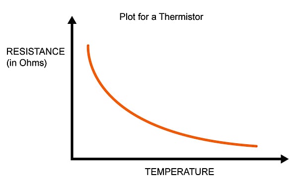
The units are shown but not the actual values as a thermistor can tailor to different ranges depending on which you buy. As you can see, the temperature gets hotter, the resistance is lower. This is a property of a Negative Temperature Coefficient resistor (NTC for short).
There are also thermistors that have Positive Temperature Coefficient (PTC for short) which means as the temperature increases, the resistance increases. However, PTC thermistors have a sort of tipping point and greatly change the resistance at some temperature. This makes the PTC thermistor a little harder to interface with. For this reason, for most low-cost temperature measurement, NTC thermistors are preferred.
For the remainder of the article, you can assume we'll be referring to NTC type thermistors.
Four Approaches to Finding a Curve Fitting Formula
Now that we better understand the general behavior of thermistors, you may start to wonder how we could possibly use an Arduino to measure temperature. The curve in the graph above is non-linear and, therefore, a simple linear equation does not seem possible. (In reality, we can work out an equation, but more on this later.)
So what to do?
Before reading on, think about how you would do this in the Arduino or even a circuit without a microprocessor component.
There are a few ways you can approach this problem, listed below. This is by no means a list of every technique out there, but it will show you some popular approaches.
Approach One:
Some manufacturers are nice enough to give you an entire chart mapping a certain integer range of temperature and resistance (typical values). One such thermistor can be found on this datasheet, by the company Vishay.
But then you think how you would do this in the Arduino. You would need to hard code all of these values into the code in a huge lookup table or a very long "switch…case" or "if…then" control structures.
And if the manufacturer is not nice enough to give a lookup table, you need to measure each point yourself to generate the data. That's a pretty bad day to be a programmer for sure. But this method is not all bad and has its place. If the project at hand only checks a few points or even a small range, this may be the preferred way to go. For example, one such situation is if you only want to measure if values fall within select temperature ranges and set up an LED to light up to indicate this situation.
But for our project, we want to measure a near-continuous range and send it to the serial monitor, so this method will not be used.
Approach Two:
You could try to “linearize” the response from the thermistor by adding external circuitry to it.
A popular way of doing this is to connect a resistor in parallel with the thermistor. Some ICs offer to do this for you.
Determining how to pick and linearize a region along with choosing the correct value is an article all by itself. This approach is great if the microprocessor does not have floating point precision (like the PICAXE) since it simplifies a range of temperature to a linear response. It also makes designing a circuit without a microprocessor easier.
But we have a microprocessor in this article and want make use of the entire range.
Approach Three:
You could take the table data from the datasheet or (if you enjoy punishing yourself) generate your own data that you made with independent measurements and recreate the plot in something like Excel. Then, you can use the curve fitting feature to create a formula for the curve. This is not a bad idea and all of the work performed will give a nice formula in your program—but it does take some time and preprocessing of data.
Although this is a legitimate approach, we do not want to be stuck analyzing all of this data. Plus, every thermistor is slightly different (but, of course, this is not really an issue if the tolerance is pretty low).
Approach Four:
Turns out there is a general curve fitting formula meant for devices like thermistors. It is called the Steinhart-Hart equation. A version of it is shown below (other versions use the squared term as well as the cubed term):
$$\frac{1}{T}=A+B\ln(R)+C(\ln(R))^3$$
where R is the resistance of the thermistor at temperature T (in kelvins).
This is a general curve fitting equation to accommodate all NTC type resistors. The approximation of the relationship of temperature and resistance is “good enough” for most applications.
Note that the equation needs the constants A, B, and C. These are different for each thermistor and need to be either given or calculated. Since there are three unknowns, you need three measurements of resistance at a certain temperature which then can be used to create three equations to solve for these constants.
Even for those of us that are algebraic wizards, this is still too much work.
Instead, there is a simpler equation that is less accurate but has only one constant. The constant is denoted by β, and thus the equation is referred to as the β equation.
$$\frac{1}{T}=\frac{1}{T_o}+(\frac{1}{\beta})\cdot\ln\left(\frac{R}{R_o}\right)$$
where Ro is the resistance at reference temperature To (e.g., the resistance at room temperature). β is usually given in the datasheet—and if not, you only need one measurement (one equation) to calculate for it. This is the equation that I will be using for our thermistor interface as it is pretty straightforward to code and is the simplest one I have encountered without needing to linearize the thermistor’s response.
Measuring Resistance with the Arduino
Now that we've got our approach out of the way, we need to figure out how to actually measure the resistance with the Arduino before we can feed this info into the β equation. We can do this using a voltage divider:
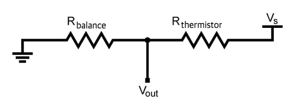
This will be our interface circuit to our thermistor. When the thermistor senses a change in temperature, this will be reflected in the output voltage.
Now, usually, we use a voltage divider with the equation below:
\[V_{out}=V_{s}\cdot(\frac{R_{balance}}{R_{thermistor}+R_{balance}})\]
But we do not want Vout as the answer—we want Rthermistor. So let us solve for that using algebra magic:
\[R_{thermistor}=R_{balance}\cdot(\frac{V_s}{V_{out}}-1)\]
This is almost perfect but we need to measure our voltage output now as well as the supply voltage. This is where we make some good use of the Arduino’s built-in ADC. (If you're not familiar with the concept, please refer to AAC's textbook entry on ADCs for some background information.)
We can represent the voltage as a digital number within a certain scale. So really, our equation finally winds up like below:
\[R_{thermistor}=R_{balance}\cdot(\frac{D_{max}}{D_{measured}}-1)\]
This works out mathematically because no matter how we represent the voltage (in volts or in digital units), these units cancel out top and bottom in the fraction, leaving a dimensionless number. Then, multiply by a resistance to yield an answer in ohms.
Dmax for us will be 1023 since this is the highest number generated by our 10 bit ADC. Dmeasured will be the measured ADC value, which could be as low as zero and as high as 1023.
Phew! Onward to building it!
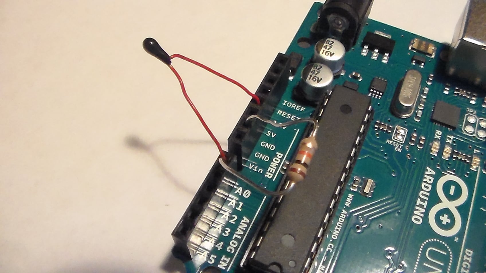
Wiring It Up
I used a TH10K thermistor.
I also used a 10k ohm resistor for Rbalance in our voltage divider. There was no β given so I needed to calculate that, myself.
Below is a complete schematic. It is actually pretty easy and straightforward!
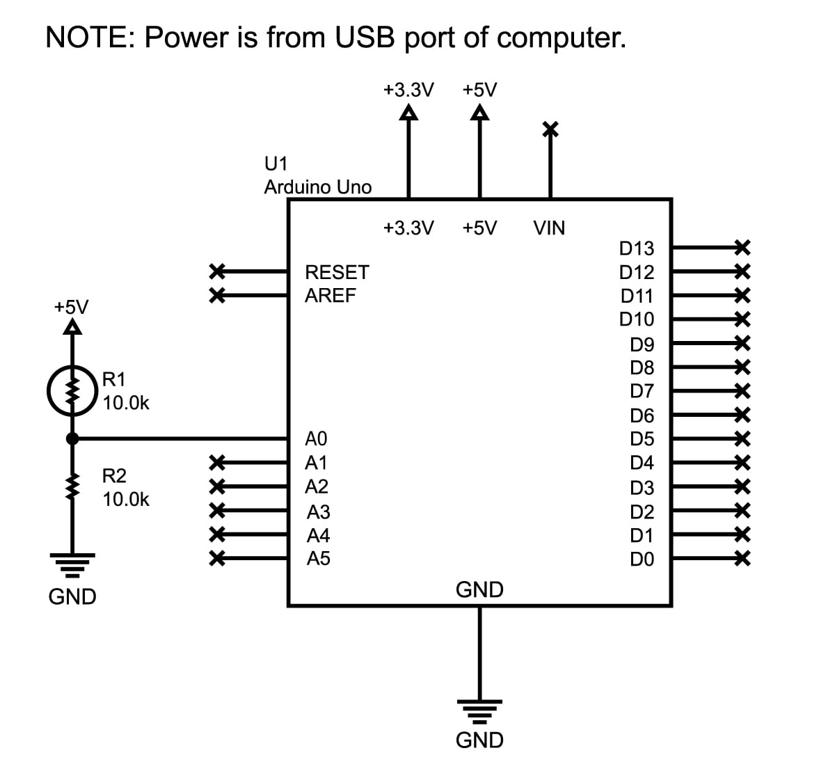
Click to enlarge.
And here's what my setup ended up looking like:
Arduino Code
The code here has been laid out with much thought and has a copious amount of comments to help you get through the logic.
Basically, it measures the divider's voltage, calculates the temperature, and then shows this in the serial terminal.
For fun, there are also some "if…then" statements to show how you can act upon a range of temperatures and a single data point.
As always, comment below for questions! Or slap this in the forum for detailed responses—everyone there is pretty friendly and will help you with any issue (within the forum rules).
/*
================================================================================

    File........... Thermistor_Demo_Code
    Purpose........ Thermistor demonstration code
    Author......... Joseph Corleto
    E-mail......... corleto.joseph@gmail.com
    Started........ 7/25/2016
    Finished....... 7/25/2016
    Updated........ --/--/----

================================================================================
   Notes
================================================================================

================================================================================
  Updates
================================================================================
*/

//===============================================================================
//  Header Files
//===============================================================================

//===============================================================================
//  Constants
//===============================================================================
//Thermistor related:

/* Here we have a few constants that make editing the code easier. I will go
   through them one by one.

   A reading from the ADC might give one value at one sample and then a little
   different the next time around. To eliminate noisy readings, we can sample
   the ADC pin a few times and then average the samples to get something more
   solid. This constant is utilized in the readThermistor function.
   */
const int    SAMPLE_NUMBER      = 10;

/* In order to use the Beta equation, we must know our other resistor
   within our resistor divider. If you are using something with large tolerance,
   like at 5% or even 1%, measure it and place your result here in ohms. */
const double BALANCE_RESISTOR   = 9710.0;

// This helps calculate the thermistor's resistance (check article for details).
const double MAX_ADC            = 1023.0;

/* This is thermistor dependent and it should be in the datasheet, or refer to the
   article for how to calculate it using the Beta equation.
   I had to do this, but I would try to get a thermistor with a known
   beta if you want to avoid empirical calculations. */
const double BETA               = 3974.0;

/* This is also needed for the conversion equation as "typical" room temperature
   is needed as an input. */
const double ROOM_TEMP          = 298.15;   // room temperature in Kelvin

/* Thermistors will have a typical resistance at room temperature so write this
   down here. Again, needed for conversion equations. */
const double RESISTOR_ROOM_TEMP = 10000.0;

//===============================================================================
//  Variables
//===============================================================================
// Here is where we will save the current temperature
double currentTemperature = 0;

//===============================================================================
//  Pin Declarations
//===============================================================================
//Inputs:
int thermistorPin = 0;  // Where the ADC samples the resistor divider's output

//Outputs:

//===============================================================================
//  Initialization
//===============================================================================
void setup()
{
  // Set the port speed for serial window messages
  Serial.begin(9600);
}

//===============================================================================
//  Main
//===============================================================================
void loop()
{
  /* The main loop is pretty simple, it prints what the temperature is in the
     serial window. The heart of the program is within the readThermistor
     function. */
  currentTemperature = readThermistor();
  delay(3000);

  /* Here is how you can act upon a temperature that is too hot,
  too cold or just right. */
  if (currentTemperature > 21.0 && currentTemperature < 24.0)
  {
    Serial.print("It is ");
    Serial.print(currentTemperature);
    Serial.println("C. Ahhh, very nice temperature.");
  }
  else if (currentTemperature >= 24.0)
  {
    Serial.print("It is ");
    Serial.print(currentTemperature);
    Serial.println("C. I feel like a hot tamale!");
  }
  else
  {
    Serial.print("It is ");
    Serial.print(currentTemperature);
    Serial.println("C. Brrrrrr, it's COLD!");
  }
}

//===============================================================================
//  Functions
//===============================================================================
/////////////////////////////
////// readThermistor ///////
/////////////////////////////
/*
This function reads the analog pin as shown below. Converts voltage signal
to a digital representation with analog to digital conversion. However, this is
done multiple times so that we can average it to eliminate measurement errors.
This averaged number is then used to calculate the resistance of the thermistor.
After this, the resistance is used to calculate the temperature of the
thermistor. Finally, the temperature is converted to celsius. Please refer to
the allaboutcircuits.com article for the specifics and general theory of this
process.

Quick Schematic in case you are too lazy to look at the site :P

          (Ground) ----\/\/\/-------|-------\/\/\/---- V_supply
                     R_balance      |     R_thermistor
                                    |
                               Analog Pin
*/

double readThermistor()
{
  // variables that live in this function
  double rThermistor = 0;            // Holds thermistor resistance value
  double tKelvin     = 0;            // Holds calculated temperature
  double tCelsius    = 0;            // Hold temperature in celsius
  double adcAverage  = 0;            // Holds the average voltage measurement
  int    adcSamples[SAMPLE_NUMBER];  // Array to hold each voltage measurement

  /* Calculate thermistor's average resistance:
     As mentioned in the top of the code, we will sample the ADC pin a few times
     to get a bunch of samples. A slight delay is added to properly have the
     analogRead function sample properly */

  for (int i = 0; i < SAMPLE_NUMBER; i++)
  {
    adcSamples[i] = analogRead(thermistorPin);  // read from pin and store
    delay(10);        // wait 10 milliseconds
  }

  /* Then, we will simply average all of those samples up for a "stiffer"
     measurement. */
  for (int i = 0; i < SAMPLE_NUMBER; i++)
  {
    adcAverage += adcSamples[i];      // add all samples up . . .
  }
  adcAverage /= SAMPLE_NUMBER;        // . . . average it w/ divide

  /* Here we calculate the thermistor’s resistance using the equation
     discussed in the article. */
  rThermistor = BALANCE_RESISTOR * ( (MAX_ADC / adcAverage) - 1);

  /* Here is where the Beta equation is used, but it is different
     from what the article describes. Don't worry! It has been rearranged
     algebraically to give a "better" looking formula. I encourage you
     to try to manipulate the equation from the article yourself to get
     better at algebra. And if not, just use what is shown here and take it
     for granted or input the formula directly from the article, exactly
     as it is shown. Either way will work! */
  tKelvin = (BETA * ROOM_TEMP) /
            (BETA + (ROOM_TEMP * log(rThermistor / RESISTOR_ROOM_TEMP)));

  /* I will use the units of Celsius to indicate temperature. I did this
     just so I can see the typical room temperature, which is 25 degrees
     Celsius, when I first try the program out. I prefer Fahrenheit, but
     I leave it up to you to either change this function, or create
     another function which converts between the two units. */
  tCelsius = tKelvin - 273.15;  // convert kelvin to celsius

  return tCelsius;    // Return the temperature in Celsius
}
Possible Next Steps
Everything in this article shows a pretty simple way of measuring temperature with a cheap thermistor. There are a couple of ways you could improve on the setup:
- Put a small capacitor in parallel with the output voltage. This would stabilize the voltage and might even eliminate the need to average many samples (as in the code)—or at least you could average fewer samples.
- Use precision resistors (better than 1%) to have a more consistent and predictable measurement. If you need absolute critical temperature measurement, keep in mind that self-heating of the thermistor can influence measurements; this project does not compensate for self-heating.
Of course, thermistors are just one sensor used for temperature measurements. Another popular choice is to use a temperature IC like this one (PDF). That way you never need to deal with linearization or complicated equations. Two other options are a thermocouple and an IR type sensor; the latter can measure temperature without physical contact, but they're not cheap.
I hope this gives you a better idea on how to measure temperature for your next project!
Thermistor_Demonstration_Code.zip
Give this project a try for yourself! Get the BOM.


This formula is incorrect:
Rthermistor=Rbalance⋅(DmaxDmeasured−1)
It should be divided by, not multiplied by:
Rthermistor=Rbalance / (DmaxDmeasured−1)
How would I go about using two thermistors in the same code to measure separate temperatures at the same time? Thanks!