Facebook
 Google
 GitHub
 Linkedin
Programming Your Standalone Hardware Soundboard
In Part 2 of this two-part series, we turn our hardware assembly into a functioning soundboard by adding the necessary code in Arduino IDE and uploading soundbites.
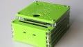
In the first half of this project, we reverse-engineered a smart voice module and designed a custom button matrix keypad. We then wired these components to an ATmega328 microcontroller to create the soundboard device you see in Figure 1.
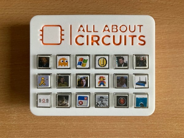
Figure 1. The All About Circuits hardware soundboard in its 3D printed case.
Now, in Part 2, we’ll complete this project by going through the Arduino code that will make the soundboard run. We’ll also discuss how to upload soundbites to its memory and properly organize them.
Note: You will need to build the circuit from “Craft Your Own Hardware Soundboard Using an Arduino Microcontroller” before proceeding. In addition to assembly instructions, this article contains the BoM, circuit schematic, CAD files, and STL files for the soundboard project.
Creating an Arduino Sketch
To start writing code, we first need to create a new sketch in the Arduino IDE. We’ll simplify our design by including two freely available libraries in our code header:
#include <DYPlayerArduino.h>
#include <Keypad.h>
The DYPlayerArduino.h library implements the DY1703A’s proprietary communications protocol as convenient and easy-to-use C++ functions. This allows us to forgo sending commands to the IC manually. The Keypad.h library helps us read our button matrix keys.
Defining Objects, Variables, and Constants
Our next step is to create a player module object:
DY::Player player;
After that, we’ll declare and initialize a 6-by-3 character matrix:
const byte ROWS = 6;
const byte COLS = 3;
The matrix uses 18 sequential letters to represent our 18 buttons.
char hexaKeys[ROWS][COLS] = {
  { 'a', 'b', 'c' },
  { 'd', 'e', 'f' },
  { 'g', 'h', 'i' },
  { 'j', 'k', 'l' },
  { 'm', 'n', 'o' },
  { 'p', 'q', 'r' }
};
Once that’s done, we’ll define the GPIO pins where each row and column bus will connect to our microcontroller:
byte rowPins[ROWS] = { 14, 15, 16, 17, 18, 19 };
byte colPins[COLS] = { 2, 3, 4 };
Finally, we initialize a keypad object instance using these matrix variables as its arguments:
Keypad customKeypad = Keypad(makeKeymap(hexaKeys), rowPins, colPins, ROWS, COLS);
Character to Index Offset
To access a file in memory, we need to use its index value. Since we have 18 soundbites, the index will be represented by an integer value between 1 and 18. However, the file index isn’t what the keyboard detects when a button is pressed. Instead, the button’s value registers as one of the lowercase letters we just defined as elements in the character matrix.
To convert that character’s ASCII number to an integer within the file index range, we need to create an offset constant. Because the letter “a” has a decimal ASCII value of 97, we’ll use an offset constant value of 96:
const char asciiOffset = 96;
Setup Function
Our sketch’s setup function initializes the player object we created and adjusts its volume. In the code snippet below, I set the volume to 20 percent.
player.begin();
player.setVolume(20);
Loop Function
The last piece of code we need to include is our sketch’s loop function. First, we need to declare a variable that will save the character value of a key whenever one is pressed. To scan the button matrix and determine which button has actually been pressed, we use the following get function from the keypad library:
char customKey = customKeypad.getKey();
The customKey variable now contains the ASCII character value from the button push. We subtract the ASCII offset constant from this key value to obtain our file index. We then call a play function with that file index as its argument and wait a certain period of time for it to play (I’ve set it to 1,000 ms):
if (customKey) {
    int fileIndex=customKey-asciiOffset;
    player.playSpecified(fileIndex);
    delay(1000);
}
This procedure gets the DY1703A to fetch a file with a certain index from its flash memory, decode that file’s MP3 signal, and then send it to the LTK5128’s input to be amplified and played by the speaker connected to its output.
Uploading the Code
Now that our code is finished, we can go ahead and upload it. If you’re using an Arduino development board, this process is straightforward. If you’re using just the microcontroller, follow the steps in Arduino’s “From Arduino to a Microcontroller on a Breadboard” tutorial and use a USB-to-serial module to program it.
Adding Soundbites
Millions of soundbites are available from all over the internet. Just choose the ones you want, download them, and drop them into your soundboard’s flash memory using the device’s USB port. It’s best practice to name the soundbites sequentially (00001.mp3, 00002.mp3, 00003.mp3, and so on) before loading them onto the W25Q32.
Your Turn
As of now, our soundboard is completely built and programmed. Figure 2 demonstrates its operation.
Figure 2. The completed soundboard in operation. [video]
You’ve seen my version of the soundboard—now it’s time to build your own. To make things more convenient, all of the code in this article is available for download below:
All About Circuits Soundboard .ino File
You can expand this circuit and its code by adding additional audio files and buttons, or add support for stereo sound by using an extra speaker and a more advanced amplifier. You might even consider adding a potentiometer to adjust the speaker’s audio. And, of course, there are always ways to optimize the keypad scanning code by using different libraries or functions.
My goal with this project was to walk through the process of designing a fully-fledged embedded system that’s not only fun to make, but also fun to play around with. Let me know in the comments if you built this project, what soundbites you chose, and how you’ve expanded it!
All images used courtesy of Kristijan Nelkovski