Facebook
 Google
 GitHub
 Linkedin
Craft Your Own Hardware Soundboard Using an Arduino Microcontroller
Learn how to turn an ATmega328 microcontroller and an assortment of readily available parts into a dedicated hardware soundboard.
In broadcasting, the word ‘soundboard’ can refer to any of several different tools—hardware or software—designed to play short audio clips throughout the duration of a program. Some soundboards are user-programmable, while others come pre-programmed with soundbites such as laugh tracks, applause effects, music snippets, or catalogues of celebrity quotes. In this project, we’ll create a customizable hardware soundboard using an ATmega328 as the brains, a reverse-engineered smart voice module for playing audio, and a button matrix for a keypad.
To make things easier to follow, I’ve split the project into two parts. Part 1, which you’re reading now, covers the hardware build. In Part 2, we’ll walk through the process of programming the soundboard. Figure 1 shows the final product in operation.
Figure 1. The completed custom soundboard. Watch with sound on. [video]
Project Requirements and BoM
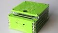
For this project, I designed a custom printed circuit board (Figure 2) along with the 3D printed case you saw in the introductory video.

Figure 2. An All About Circuits PCB I designed for this project.
The CAD files for the circuit board and the STL files for the case are both available for download below:
If you don’t want to go the extra mile, you can still create a functional soundboard using the following:
- Any Arduino-compatible development board.
- A DY-SV17F audio module.
- A pre-built button matrix keypad.
Keep in mind that you’ll need to adjust the project code based on the type and number of keys on your chosen keypad. Otherwise, Table 1 provides the full bill of materials (BoM) for the project.
Table 1. Project bill of materials.
| Part | Quantity | Notes |
| ATmega328 (or any Arduino-compatible development board) | 1 | The brains of our project. |
| DY1703A | 1 | Sound player. |
| W25Q32 | 1 | Flash memory. |
| LTK5128 | 1 | Audio amplifier. |
| Speaker | 1 | For audio. |
| 12 mm-by-12 mm tactile buttons | 18 | For the button matrix. |
| 1n4148 diodes | 18 | For the button matrix. |
| 1 μf capacitor | 5 | C1-C4, C9 |
| 22 nf capacitor | 1 | C5 |
| 470 nf capacitor | 1 | C6 |
| 470 μf capacitor | 1 | C7 |
| 1 μf capacitor (electrolytic) | 1 | C8 |
| 0.1 μf capacitor | 1 | C10 |
| 47 μf capacitor (electrolytic) | 1 | C11 |
| 10 μf capacitor (electrolytic) | 1 | C12 |
| 22 pf capacitor | 2 | C13, C14 |
| 100 Ω resistor | 1 | R1 |
| 100 kΩ resistor | 1 | R2 |
| 3.3 kΩ resistor | 2 | R3, R4 |
| 270 Ω resistor | 1 | R5 |
| 820 Ω resistor | 1 | R6 |
| 10 kΩ resistor | 9 | R7-R9, R12-R17 |
| 1 kΩ resistor | 2 | R10, R11 |
| S8050 transistor | 1 | For controlling the amplifier. |
| USB-B connector | 1 | For loading data using the computer. |
| ON/OFF switch | 1 | For switching between USB and battery power. |
| AMS1117-adj | 1 | Voltage regulator. |
| Pin headers | As needed | For connecting to a battery, a programmer, and the speaker. |
Project Schematic
Figure 3 shows the full circuit schematic for the soundboard.

Figure 3. Circuit schematic for the soundboard. [click to enlarge]
Let’s explore the audio and button matrix portions of this schematic. Discussion of the microcontroller will mostly wait until the next article—unlike the voice module and the keypad, there’s not much assembly that needs to be done there.
Storing and Playing Audio
The first item on our BoM after the ATmega328 is the DY1703A, a dedicated audio player chip that offers controls for playing, pausing, and selecting music, as well as adjusting the volume of its output. This IC supports common sampling rates ranging from 8 kHz to 48 kHz and is capable of decoding MP3 and WAV file formats. It typically interfaces with either a flash memory chip (which is what we’re using) or an SD card.
We’ll store the audio files on the W25Q32 low-powered serial NOR flash memory, which has a capacity of 32 Mb (4 MB). Although this chip can be programmed using SPI, we’re going to access it as a mass storage device via USB and load data through the computer—just like we would on a thumb drive or an SD card.
The DY1703A includes seven selectable operating modes via 3 config and 8 I/O pins. We’ll transfer the audio file data to the microcontroller using a UART connection of I/O pins 0 and 1 (TX and RX). This will allow us to select from up to 65,000 pieces of music simply by sending two 8-bit snippets of data sandwiched between a couple of command codes (16 bits equals 65,536 states).
Finally, we’ll use the LTK5128 5 W mono audio amplifier chip to build a simple Class D switching amplifier, which will drive an 8 Ω speaker. This IC reportedly can achieve an efficiency of above 90 percent, which is typical for switching amplifiers.
Button Matrix
Now that we’ve got audio sorted out, we need a way to select individual soundbites. For our project, I chose the 12 mm tactile buttons in Figure 4. They have detachable transparent covers, which allowed me to easily print out a small image corresponding to each soundbite and place it underneath the cover.

Figure 4. For easy customization, I chose buttons with detachable covers.
I designed this soundboard to have 18 different soundbites. We’ll therefore build a button matrix with 18 buttons in a formation of six rows by three columns. One terminal of each button will be connected to every other button in its row. Another terminal of each button will be connected to every other button in its column. Pressing a button closes the circuit between the associated row and column, allowing current to flow.
The microcontroller detects the row and column selected by each button press. This allows us to use only nine GPIO pins: six for the rows and three for the columns. We would need 18 GPIO pins if we wanted to detect each button press individually.
To ensure the button matrix functions properly, we also need to do the following:
- Connect each button to a row bus using a diode.
- Pull each column bus to VCC using a resistor.
These extra steps represent common methods used by engineers when designing keyboards and keypads to prevent issues such as ghosting and debouncing.
One Part Down, One to Go
Once we’ve wired everything up, the hardware portion of this project is complete. In the second half of this two-part series, we’ll make this soundboard run by writing some Arduino code and organizing and attaching some soundbites to its memory.
Background of featured image created using Canva; all other images used courtesy of Kristijan Nelkovski