Facebook
 Google
 GitHub
 Linkedin
Reading Sensors with an Arduino
The ease with which an Arduino can obtain sensor values is one of the features that makes it so useful.
The ease with which an Arduino can obtain sensor values is one of the features that makes it so useful.
Sensors are devices that convert a physical quantity, such as light intensity or temperature, into an electrical quantity. A thermocouple, for example, outputs a voltage proportional to its temperature. There are many different types of sensors:
- Light sensor
- Motion sensor
- Temperature sensor
- Magnetic fields sensor
- Gravity sensor
- Humidity sensor
- Moisture sensor
- Vibration sensor
- Pressure sensor
- Electrical fields sensor
- Sound sensor
- Position sensor
These sensors are used in thousands of different applications, including manufacturing, machinery, aerospace, automobiles, medicine, and robotics.
EXPERIMENT 1: Distance sensor
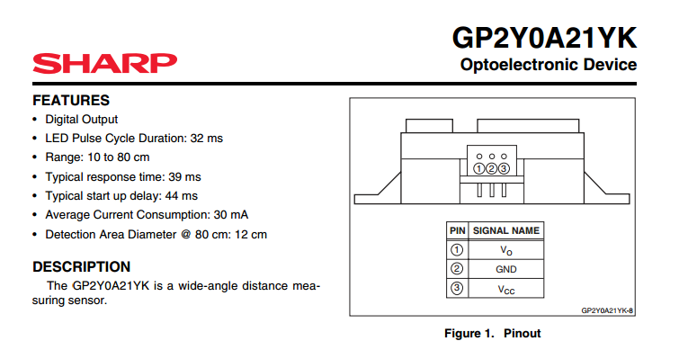
In this experiment, we will use a Sharp GP2Y0A21YK proximity sensor to control the brightness of an LED.
SHARP IR Sensor
Hardware Required
- 1 x Arduino Mega2560
- 1 x breadboard
- 1 x LED
- 5 x jumper wires
- 1 x 470 ohm resistor
- 1 X Sharp GP2Y0A21YK proximity sensor
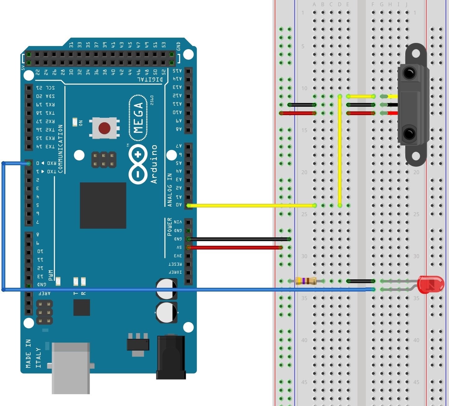
Wiring Diagram
Circuit Diagram
The Sharp proximity sensor can detect objects as close as 10 cm and as far away as 80 cm. It emits a pulse of infrared light and then detects the angle at which that light is reflected. The farther away an object is, the lower the output voltage. If the sensor receives no reflection, the output voltage of the sensor will be 0 V. If the object is 10 cm or closer, the output voltage will be equal to 5 V. (In this experiment, we are supplying 5V to the sensor.)
The sensor's output is connected to an Arduino analog input. The Arduino's analog-to-digital converter (ADC) then converts that value to a value between 0 and 1023. This value is then mapped to a value between 0 and 255, and that number is used to set the duty cycle of a pulse-width modulated output, which controls the brightness of the LED. The result is that the closer an object is to the proximity sensor, the brighter the LED will shine.
Code For Experiment 1
const int pwm = 2 ; //Initializing Pin for pwm const int adc = A0 ; //Initializing Pin for adc void setup() { pinMode(pwm,OUTPUT) ; // To change LED brightness } void loop() { int sensor_val = analogRead(adc) ; sensor_val = map(sensor_val, 0, 1023, 0, 255) ; /* -----------map funtion------------ The above funtion scales the output of adc,which is 10 bit and gives values btw 0 to 1023, in values btw 0 to 255 form analogWrite funtion which only recieves values btw this range. */ analogWrite(pwm,sensor_val) ; // setting sensor value as pwm }Reading_Sensors_With_Arduino.zip
EXPERIMENT 2: Heat Sensor
In this experiment, the Arduino will measure the temperature using an LM35 sensor IC. The LM35 is a low voltage IC which requires a power supply from +4 VDC to +20 VDC. This is ideal because we can power the sensor with the Arduino's +5 V output. The LM35 has just 3 pins, 2 for the power supply and one for the analog output. The output pin provides an analog voltage output that is linearly proportional to the temperature in degrees C. The output ranges from 0 V - 1.5 V, when powered with a single power supply. An output of 0 V corresponds to a temperature of 0 degrees C, and the output increases 10 mV for every degree increase in the temperature. To convert the output voltage to temperature, you need only to divide the output voltage in mV by 10. For example, if the output value equals 315 mV (0.315 V), the temperature is 31.5°C.
Pin Configuration of LM35 IC:
Pin Configuration
Hardware Required

- 1 x LM35 Temperature Sensor
- 2 x LEDs
- 1 x matchbox
- 2 X 470 ohm resistors
- 1 x Arduino Mega2560
- 1 x breadboard
- 10 x jumper wires
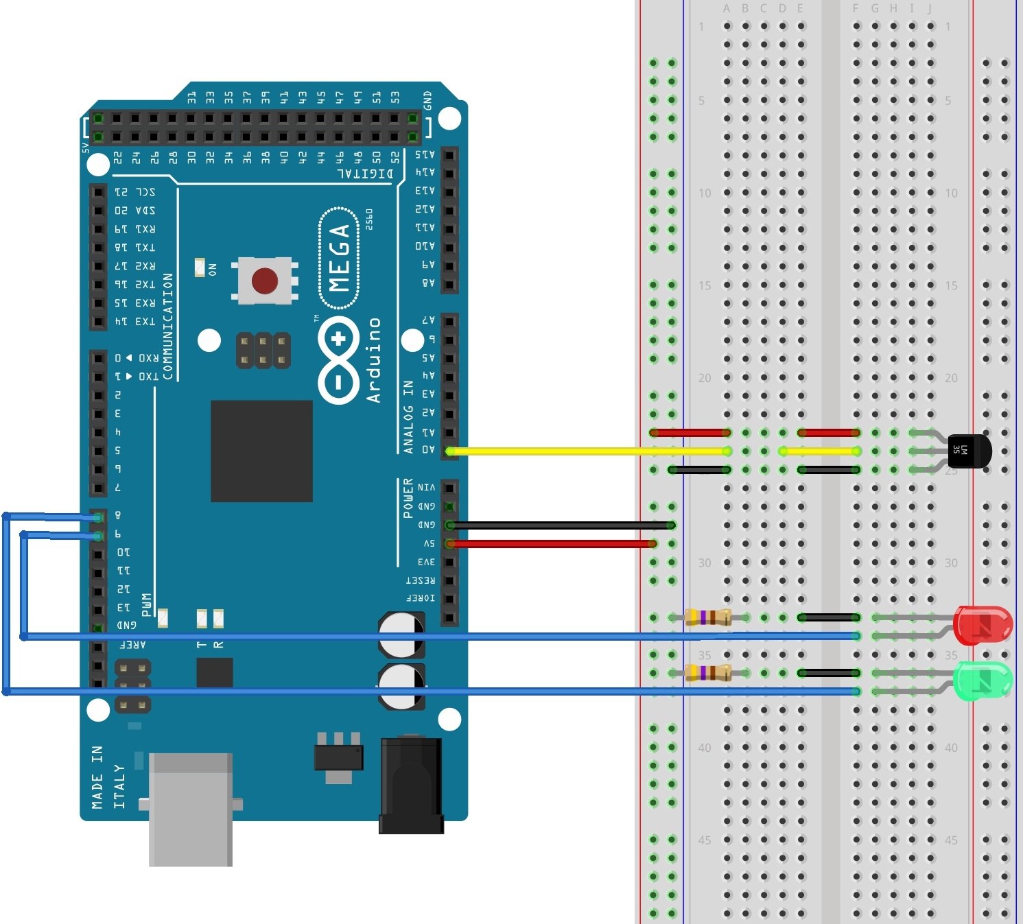
Wiring Diagram
Circuit Diagram
Code For Experiment 2
The LM35's output pin (pin 2) is connected to A0 of the Arduino. The code uses the function analogRead() to convert the output voltage to a number between 0 and 1023. Multiplying this number by 0.48828125 converts that value to degrees C, which is then displayed on the serial monitor:
const int adc = 0 ; //naming pin 0 of analog input side as adc const int high = 8 ; // For turning on and off yellow LED const int low = 9 ; // For turning on and off Green LED void setup() { Serial.begin(9600) ; //Starting serial Communication at baud rate of 9600 pinMode(high,OUTPUT); //declaring LED pins as OUTPUT pinMode(low,OUTPUT); } void loop() { int adc = analogRead(0) ; //reading analog voltage and storing it in an integer adc = adc * 0.48828125; //converting reading into Celsius Serial.print("TEMPRATURE = "); //to Display on serial monitor Serial.print(adc); //Temperature reading Serial.print("*C"); //TEMPRATURE = 27*C ETC Serial.println(); //To end the line delay(1000); //1 Sec delay /* LOGIC: if (temperature (adc) > 70 ° C ) turn on Yellow Leds turn off Green Leds else turn off Yellow Leds turn on Green Led */ if(adc>70) // This is the control statement { digitalWrite(high,HIGH) ; digitalWrite(low,LOW) ; } else { digitalWrite(high,LOW) ; digitalWrite(low,HIGH) ; }Reading_Sensors_With_Arduino2.zip
Videos
Give this project a try for yourself! Get the BOM.