Facebook
 Google
 GitHub
 Linkedin
The Closed-Loop Brushless Motor Adapter: A Tachometer-Free Speed Feedback Module
Learn how to build a closed-loop speed feedback adapter for brushless DC motors using the MC33039.
This adapter converts the Hall sensor signals of a brushless DC (BLDC) motor into a voltage that is proportional to motor speed. A motor controller can use this signal for closed-loop speed regulation, so the system does not need a magnetic or optical tachometer. The design is built around the Onsemi MC33039 closed-loop brushless motor adapter IC (Figure 1).
The MC33039 contains three input buffers with hysteresis, three digital edge detectors, a programmable monostable, and an internal shunt regulator. It also provides an inverter output for systems that need to convert sensor phasing. The IC is intended for use with the Onsemi MC33035 brushless motor controller, but it works in many other closed-loop speed control applications.
The module connects to the motor through a 9-pin Hall sensor header (CN2). A second 4-pin header (CN1) carries the supply, the frequency output, and the inverted sensor output. A power LED indicates that the board is energized.
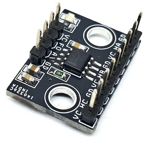
Figure 1. The assembled Closed-Loop Brushless Motor Adapter.
Specs and Features
- Power input: 5 V DC
- Digital detection of each input transition for improved low-speed motor operation
- TTL-compatible inputs with hysteresis
- Operation down to 5.5 V for direct powering from the MC33035 reference
- Internal shunt regulator for operation from an unregulated voltage source
- Inverter output for converting between 60°/300° and 120°/240° sensor phasing conventions
- Output pulse width set by R2 and C3 (950 µs with R2 = 43 kΩ and C3 = 22 nF)
- PCB dimensions: 23.65 × 16.99 mm
How It Works
The three inputs of the MC33039 (pins 1, 2, and 3) monitor the Hall sensors of the motor. Figure 2 shows the internal block diagram. Each sensor signal passes through a buffer with hysteresis and an edge detector. The edge detector outputs are ORed together at the latch set input.
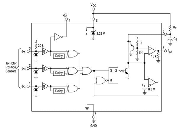
Figure 2. Representative block diagram of the MC33039. Image used courtesy of onsemi.
Every sensor transition sets the latch and discharges the timing capacitor (C3). The device then generates a pulse at the frequency output (FOUT, pin 5). The pulse has a fixed amplitude and a width set by the timing resistor and capacitor connected to pin 6 (R2 and C3). Figure 3 shows the timing for a typical three-phase, six-step motor application.
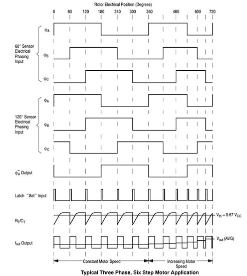
Figure 3. Typical timing diagram for a three-phase, six-step motor application. Image used courtesy of onsemi.
The average voltage of the pulse train increases with motor speed. A low-pass filter or integrator turns this pulse train into a DC voltage proportional to speed. Constant-speed operation down to 100 RPM is possible with economical three-phase, four-pole motors.
The inverted output (pin 4) is used when the sensor phasing of the motor does not match the convention of the controller. The pulse amplitude is constant over temperature and is set by the supply voltage on VCC (pin 8). Operation down to 5.5 V is guaranteed over temperature. For systems without a regulated supply, an internal 8.25 V shunt regulator is provided. Figure 4 shows the MC33039 connected to an MC33035 brushless motor controller.
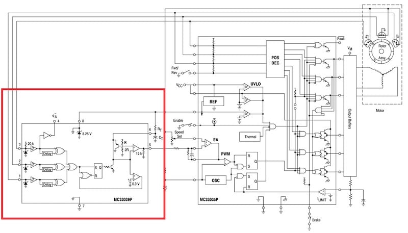
Figure 4. The MC33039 (highlighted) is used with the MC33035 brushless motor controller. Image used courtesy of onsemi.
Schematic and Bill of Materials
Figure 5 shows the schematic of the module. R1 limits the current through the power LED (D1). C1 and C2 decouple the supply. R2 and C3 set the output pulse width.
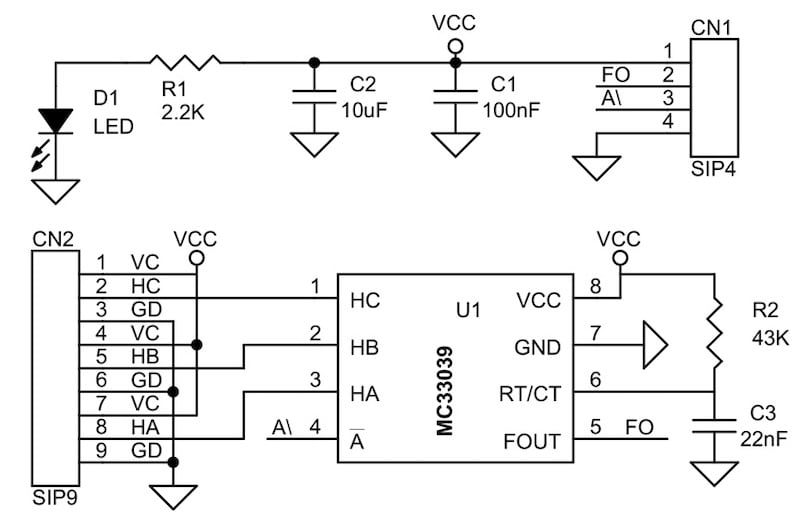
Figure 5. Schematic of the Closed-Loop Brushless Motor Adapter.
The bill of materials is shown in Table 1.
Table 1. BOM for the Closed-Loop Brushless Motor Adapter.
| REF | DESCRIPTION | QTY | MFG | SUPPLIER | PART NO. |
| CN1 | 4-pin male header, 2.54 mm pitch | 1 | Wurth | DigiKey | 732-5317-ND |
| CN2 | 9-pin male header, 2.54 mm pitch | 1 | Wurth | DigiKey | 732-5322-ND |
| C1 | 100 nF/50 V ceramic capacitor, 0805 | 1 | Yageo/Murata | DigiKey |
|
| C2 | 10 µF/35 V ceramic capacitor, 0805 | 1 | Yageo/Murata | DigiKey |
|
| C3 | 22 nF/50 V ceramic capacitor, 0805 | 1 | Yageo/Murata | DigiKey |
|
| D1 | Red LED, 0805 | 1 | OSRAM | DigiKey | 475-1278-1-ND |
| R1 | 2.2 kΩ, 5%, 0805 | 1 | Yageo/Murata | DigiKey |
|
| R2 | 43 kΩ, 1%, 0805 | 1 | Yageo/Murata | DigiKey |
|
| U1 | MC33039, SOIC-8 | 1 | onsemi | DigiKey | MC33039DR2GOSCT-ND |
Connections
Figure 6 shows the connector pinouts. The board has two headers: CN1 on the output side and CN2 on the Hall sensor side.
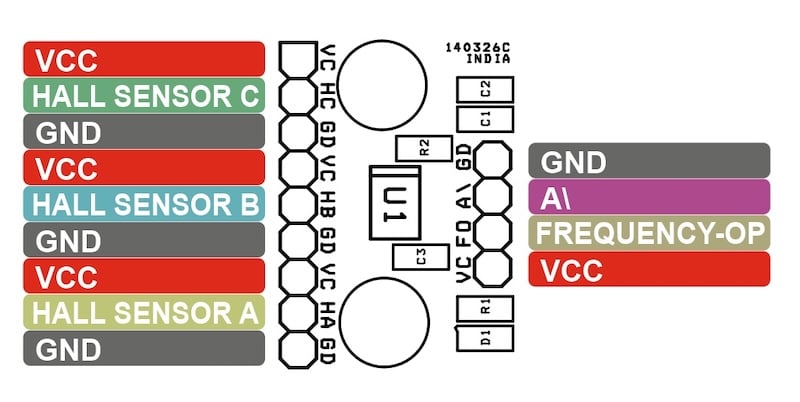
Figure 6. Connection diagram for CN1 and CN2.
CN1 — Output Header (4-pin, 2.54 mm pitch):
- Pin 1 = VCC
- Pin 2 = Frequency Output
- Pin 3 = A\ Output (inverted)
- Pin 4 = GND
CN2 — Hall Sensor Header (9-pin, 2.54 mm pitch):
- Pin 1 = VCC
- Pin 2 = Hall Sensor C
- Pin 3 = GND
- Pin 4 = VCC
- Pin 5 = Hall Sensor B
- Pin 6 = GND
- Pin 7 = VCC
- Pin 8 = Hall Sensor A
- Pin 9 = GND
D1 — Power LED
PCB Files
The board is a two-layer PCB measuring 23.65 × 16.99 mm with two mounting holes. Figure 7 shows the silk screen, top layer, and bottom layer.
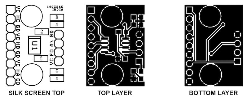
Figure 7. PCB silk screen, top layer, and bottom layer.
You can download the layout files for this project here:
Closed-Loop Brushless Motor Adapter
Except where noted, all images used courtesy of Rajkumar Sharma
Related Content