 Facebook
 Google
 GitHub
 Linkedin
Turning on a Light with Ultrasonic Motion Detection
This project will show you how to connect an ultrasonic sensor and an Arduino to turn on a light when motion is sensed.
This project will show you how to pair an ultrasonic sensor and an Arduino to turn on a light when motion is sensed.
Bill of Materials
- Arduino Uno
- NPN Transistor
- Maxbotix UltraSonic Sensor
- Wires
- Breadboard
- 1k ohm Resistor or higher
- Computer with Arduino IDE (Integrated Development Environment)
- USB Type B to connect Arduino
- Multimeter
- LED
For this project, I used a 2N3904 NPN transistor as a switch. If you don’t have a 2N3904, you can use an equivalent like the 2N2222. As long as it's an NPN, it will work with the code provided below. If you have a PNP transistor, then a change has to be made to the code (which will be described). To switch an LED on and off, these transistors will work fine. But in order to turn on a higher-powered light, like a lamp in your house, then you will need an alternate power transistor. One transistor that will be able to handle the current going through it from a power outlet is an NPN MJ15022 (PDF).
Using an Ultrasonic Sensor as a Motion Detector
Ultrasonic sensors, or sonar sensors, are a form of sensors that use echolocation to sense objects around it. It's the same principle as the echolocation that whales and bats use to find food or objects when they travel. By emitting a certain frequency and seeing how long it takes for it to come back, we can determine the location and even the speed of an object.
The ultrasonic sensor we are using has a range of up to 20 ft. It is an active sensor that is constantly emitting noise and waiting to receive it back. It can send out a new sound wave every 50ms or at a 20 Hz rate. We will be using an ultrasonic sensor as a motion detector; when there is a visible change in distance, we will consider it as an indication that an object is passing in front of the sensor. That way if you point it at your door, it will be receiving a constant distance. But as soon as someone walks by, the distance that the sonar sensor is receiving will change and we'll know that is something moving.
Since sonar sensors work using the reflection of sound waves, there might be some latency or lag when an object moves across its range. To get a perfect signal, the object would have to be flat and facing the sensor directly in order to reflect the waves back perfectly. A human body won't reflect sonar waves back perfectly, but the latency or lag shouldn’t make that big of a difference since the sound wave's radius relative to the human body is large enough to reflect the waves back. You can experiment with smaller objects to find the best wave reflection angle so that the Arduino receives the correct distance.
Using a Transistor as a Switch
The transistor is a very versatile electronic component. It can be used for switching, amplification, filtering, buffers, and regulators. In this case, we will be using it as a switch.
We have to make sure that for this tutorial you are using an NPN transistor not a PNP— otherwise, the circuit will do the opposite of what you want it to do. With a PNP transistor, the light will turn on when no motion is detected and turn off when there is motion detected. This happens because, on an NPN transistor, there is an open circuit between the collector and emitter when there is no current in the base. It’s the opposite effect for a PNP. When there is no current in the base, there is a short circuit between the collector and emitter, making it a closed circuit and allowing current to flow through.
We will be outputting to the transistor's base through the analog output A2 to open up current flow through our light source.

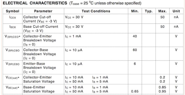
If we look at the 2N3904 datasheet (PDF), then we can read all of its electrical characteristics. The electrical characteristic we are most concerned with when using the transistor as a switch is the base-emitter saturation minimum voltage and maximum voltage.
When a transistor is operating in the saturation region, it will allow the flow of current between the emitter and the collector. When we check the datasheet of the 2N3904, we see that the minimum voltage required to operate this transistor in the saturation region is 0.65V.
If you are powering your Arduino with a battery and don’t want to send out a high output every single time it senses something, then you can change the voltage output. By default, when the Arduino outputs a HIGH it outputs 5V. But to change it to something lower, like 0.65 V or 1 Volt, then you have to change the AnalogWrite function arguments. Its current value of 255 gives out maximum (100%) duty cycle which means it gives out 5V. Using ratios, we can change the output to approximately 1 v by using the formula:
$$value = \frac{\text{voltage desired x 255}}{5}$$
If we plug in 1 v in the voltage desired part of the formula, this will give as a value of 51. I'll round it up to 50. In short, to change the output voltage to 1V, change the AnalogWrite argument to 50 so that the code looks like the code below. This way, less power is consumed and your Arduino can have a longer battery life.
analogWrite(transistor,50) ;
If you’re using another NPN transistor, check out their datasheet and pay close attention to the minimum base-emitter saturation voltage. Make sure the Arduino is outputting enough potential difference to make the transistor conduct.
Wiring Our Components on the Breadboard
Once we have all of our components ready, we want to wire them like in the figure below. In this case, we wire the transistor to be turned on through the analog output of A2. You can choose whichever output you want as long as you change it in the code.

As explained above, our analog output (which is connected to the transistor's base) will close the circuit between the 3.3V and the LED. Our 3.3V constant output from the Arduino will simulate a power outlet output.
Connect the sonar sensor as illustrated above to be able to detect motion. Use a multimeter to check that all wires are making a good connection, so that there are no unwanted short circuits or open circuits. Make sure the LED is in the correct direction— otherwise it won’t turn on.
Code
This code will be inputted on the Arduino IDE. Open the Arduino serial monitor once the code is compiled to check if the transistor is switching or not when an object passes in front of it.
#include "Maxbotix.h"   // Library for Sonar Sensor

Maxbotix rangeSensorPW(8, Maxbotix::PW, Maxbotix::LV); // Initializing Sensor Input at Digital Pin 8

int transistor = A2; // Initialzing Analog Output to Transistor at A2

void setup()
{
  pinMode(transistor, OUTPUT); // Sets the Analog A2 as an output
  Serial.begin(9600); // Starts the Serial Monitor

}

void loop()
{

  Serial.println(" ");

  Serial.print("Distance: "); // Prints Distance on the Screen
  Serial.print(rangeSensorPW.getRange());  // Receives the Distance in Cm
  Serial.print(" cm"); // Prints Cm


  if ( (rangeSensorPW.getRange()) <  48) {  // If Distance is less than 48 Cm

    Serial.println("Transistor On");  // Then the transitor turns on
    analogWrite(transistor, 255);   // Sends out 5V on Output A2
    delay(2000); // Leaves it on for 2 seconds, you can change it depending on how long you want the light on
  } //if

  else {  // Else If distance is greater than 48 cm
    analogWrite(transistor, 0);   // Turns off the Transistor
    Serial.println("Transistor Off");  // Prints Transistor Off

  }

  delay(100); // Wait 100 ms
} // loop
Once the serial monitor is opened, you will see the sensor's reading. Since in this example the code was written to detect distance/movement less than 48cm, the transistor will only turn on and activate our light if motion is detected within 48cm.
In the serial monitor below you can see how the transistor turned on when the distance changed from 172cm to 18cm.

If you prefer the imperial system (because you are in the United States, Liberia, or Myanmar) versus the metric system, you have to do a simple conversion when printing your values on the serial monitor. When the rangeSensorPw.getRange() function gets called, multiply it by 0.393701 to receive the distance in inches. If you pursue this change, then you'll have to do it for all the instances where that function is called. In the If Statements, the new condition will be in inches now. So instead of 48 cm, which is 18 inches, the new range will be 48 inches. Make sure to take that change into account and adjust your distance to what you need.
rangeSensorPw.getRange()*.393701 // To Output Distance in Inches instead of cm
Give this project a try for yourself! Get the BOM.


“If you prefer the imperial system (because you are in the United States, Liberia, or Myanmar) ...”
I live in the United States and I DON’T prefer the medieval system of units still in use here. Good Lord, when is my country going to catch up to the 20th century, when we’re already living in the 21st century?
May I know how this “Maxbotix.h” header file is made,or if possible can you upload that header file too. Because after compiling the same code as above given is generating error which means “Maxbotix.h header file is missing” .
So pls help…...Thanks