 Facebook
 Google
 GitHub
 Linkedin
Upgrade Your Power Wheels with Motor Control Basics
Adding variable speed control and battery monitoring to a Power Wheels truck!
Adding variable speed control and battery monitoring to a Power Wheels truck!
Materials
- PWM motor controller
- Used in this project: DROK 9-60V 20A 600W Switch Dimmer Governor
- If you have a larger motor you may want the 40A version, however you may hear a squeeling noise
- Used in this project: DROK 9-60V 20A 600W Switch Dimmer Governor
- Voltage and current meter
- Used in this project: DROK Volt/Amp monitor
- Spray Paint for Plastics
- Use in this project: Krylon Super Maxx
- 12V Battery
- Used in this project: UB12120
- Power Wheels Truck
Cleaning
Who didn't want a Power Wheels car as a kid?! I bought a used Power Wheels truck on Craigslist as a restoration project. Here it is in all its dirty glory! I also got a pink convertible, but that's a separate project.
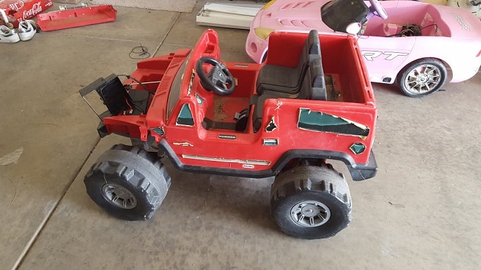
I used WD40 to clean off the stickers. After a wash with soap and water, plus some heavy spraying from the hose, the truck was looking much more respectable. If you have to hose down the truck, make sure to cover the motors with some plastic bags so water doesn't get inside.

Painting
The truck had a lot of sun fade and scratches so I wanted to clean it up before I put the new electronics in. You have to use a spray paint that can adhere to plastics. I tried Krylon Super Maxx and it came out very nice.


Motor Speed Controller
The battery that came with the truck was dead, so I bought a new one. It only had spade connectors, so I soldered some wires to the approriate connectors to connect and disconnect from the battery. I left the fuse from the previous battery in the line for protection. I chose the motor controller based on the high frequency it uses and the current/voltage it could handle. If you use a motor controller with too low of a pulse-width modulation (PWM) frequency, you can potentially hear ringing from the motors themselves.
What is PWM? In short, PWM is a way to efficiently change the voltage presented to the motor. You could do this with a resistor, but it would be very inefficient. PWM is accomplished by rapidly turning the battery on and off at a certain frequency and duty cycle. Duty cycle represents the amount of time the battery is connected to the motors. This is mathematically represented as a rectangular pulse train whos average value changes proportional to the duty cycle. This average value is what delivers power to the motor. As long as the frequency is high enough, the motor will not be affected by the rapid on and off switching. For example, if the PWM controller was set to a duty cycle of 50%, the motors would run as if they were connected to a 6V battery.
I cut the previous connector off the old battery so I could use it to connect the motor controller to the existing wiring harness, shown as a blue connector below. The wiring is fairly simple for the controller. Just make sure to use large wire and spades if possible to get solid connection using the screw terminals. Also keep in mind there is a switch inside the unit that controls the direction, so if you wire it backwards you can always flip the switch. The switch can also shut off the motor controller, so if the motor isn't working make sure the switch didn't get bumped during assembly (which I did many times!).

The motor controller is controlled using the dial on the front. If you take the motor controller apart, this dial is attached to a fairly long ribbon cable. I mounted the motor controller next to the battery. I wanted to control the speed from the driver seat, so I took advantage of this ribbon cable length to mount the dial on the dashboard. On my motor controller, I found that the ribbon cable was soldered poorly to the dial, so I was getting intermittent connections. I resoldered the connections and it worked fine. You could also incorporate speed control into the pedal if you have a potentieter type pedal laying around. I looked around the internet quite a bit and couldn't find one.

The following picture shows the various items under the hood. There is also a Bluetooth module I connected to my phone to use as a kill switch and charging cables that are not covered in this article.

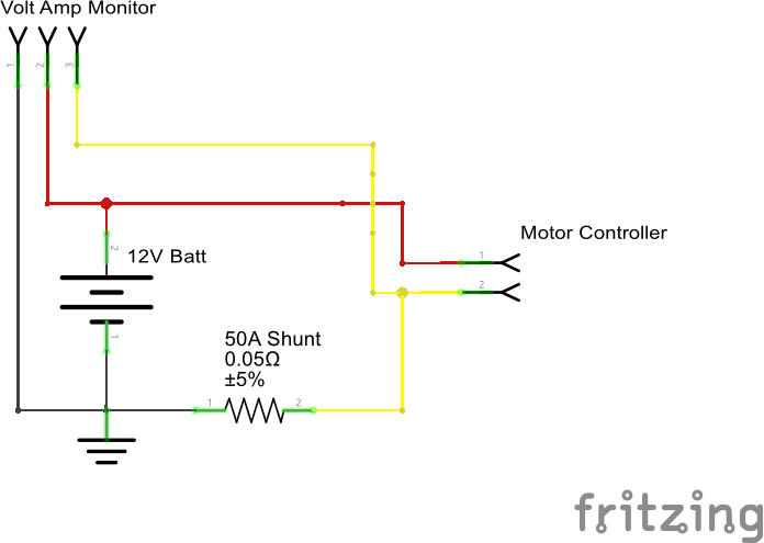
Voltage/Current Meter
I thought it would be great to know how much play time was left before the batteries died. I also wanted some indication of how much energy was being used. I opted for an LCD screen that I could mount in the dashboard. If you choose your own screen, make sure it either comes with a resistor shunt or that you purchase one separately. I noticed a lot of current meters wouldn't handle much past 10 amps without buying a separate shunt. When I was testing with two toddlers in the truck, I saw currents go as high as 15 amps. Wiring the voltage meter is as simple as connecting the wires across the battery. The current meter must be wired in series on the ground side of the battery. I mounted the shunt inside the protective battery lid and increased the length of the LCD wires to reach the dashboard.
I cut a hole in the dashboard to snap the screen into. The screen draws so little power that I just leave it on all the time.

Result

Related Content


I enjoyed this article as i found 1 -12vdc four wheeler with dead battery and then 2 - 6vdc smaller four wheelers good batt’s bad chargers. So I am placing them on my lawnmower for steering r/l and activating self propel through cable with drum drives for ratios needed and the 6 v ones for reverse through a fixie bike one way drive. All controlled with a $15 3 channel dollar store 49mhz rc car guts.Need 12v battery(used my car battery for testing) and then adapting.
would a sewing machine pedal work?