Facebook
 Google
 GitHub
 Linkedin
Choosing Inductor Values for Step-Down Switching Voltage Regulators
Proper inductor selection is one key to the successful design and implementation of a switching regulator. This article will help you understand the relationship between the inductor value and circuit performance.
A buck converter, also called a step-down converter, is a switch-mode voltage regulator that efficiently converts a DC input voltage into a lower DC output voltage. In this series of articles, we’re using LTspice to investigate the electrical behavior of a switch-mode voltage converter. This article will begin to explore the design tasks and trade-offs pertaining to the circuit’s inductor.
The LTspice schematic shown in Figure 1 will allow us to simulate the power stage of a buck converter. To be a complete converter, we would need to add a feedback control loop to regulate the voltage.
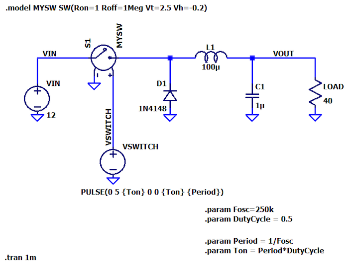
Figure 1. Buck converter power stage circuit schematic for simulation
Buck Converter Inductance Formula
An application note from Texas Instruments provides the following equation for calculating inductor size:
$$L=\frac{V_{OUT}\times\left(V_{IN}-V_{OUT}\right)}{\Delta I_L \times f_S \times V_{IN}}$$
Each of these terms requires some explanation:
VOUT: This is the regulated output voltage that you want to design for. You may end up using your regulator with a higher or lower output voltage, and that’s fine, but if you make a major change in output voltage, the converter may benefit from a new inductance value.
VIN: Similarly, we often expect a switching regulator to tolerate a range of input voltages, so if your VIN is not fixed, you can choose a value somewhere in the middle of the range.
fS (switching frequency): You have to think about the switching frequency before you can calculate the inductance value. Something between 200 kHz and 2 MHz is a reasonable starting point. If you want some guidance on whether you should favor the lower or higher end of that range, take a look at my article entitled How to Choose the Frequency of Your Switching Regulator.
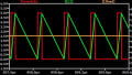
ΔIL: This denotes inductor current ripple, i.e., the peak-to-peak variation in inductor current as illustrated in Figure 2
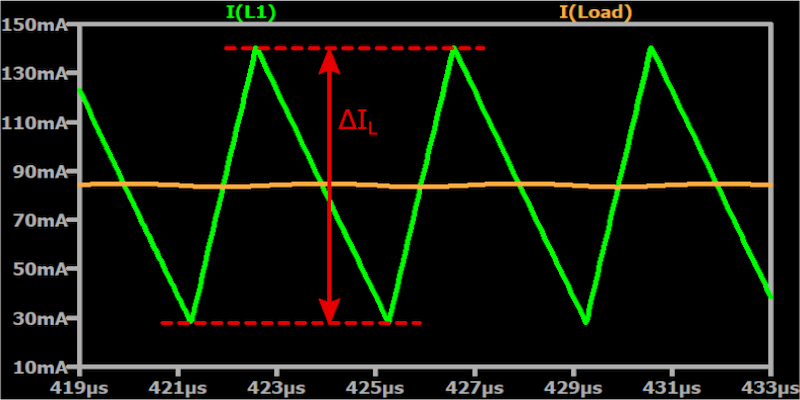
Figure 2. Buck converter inductor current ripple
In response to the on/off action of the switching element, the inductor current in a buck converter ramps up and down, extending above and below the load current (which is the average value of the inductor current). The magnitude of these deviations is expressed as inductor current ripple (ΔIL).
If we express current ripple (CR) as a percentage of the expected load current, a recommended CR spec is 30%. This means that the maximum inductor current is 15% above the expected load current, and the minimum inductor current is 15% below the expected load current.
You might see terms like “maximum load current” or “full load current” instead of “expected load current.” I interpret all of these to mean the highest load current that the regulator will need to supply on a long-term basis. I wouldn’t consider unusually high transient currents when setting a ΔIL target.
Calculating Buck Converter Inductance: An Example
Let’s work through an example of inductor sizing. We’ll change various parameters in my LTspice circuit so that we’re really doing something new here.
Let’s imagine that our objective is to accept a fairly high system voltage and generate a voltage rail suitable for a low-power, mixed-signal embedded system. We’ll say that our nominal input voltage is 24 V, and our desired output voltage is 3.3 V. The expected load current is 70 mA.
A switching regulator is preferred for this sort of application because the large input-to-output differential would only intensify a linear regulator’s inherent inefficiency.
Because we’ll be powering some analog circuitry, I want to reduce the ripple in the output voltage. Also, I’m going to opt for a higher switching frequency—let’s say 1.5 MHz—because higher switching frequencies help to reduce output ripple.
We also need to choose an initial duty cycle. For this, we can use the maximum duty cycle that the circuit will need for the specified input and output voltage, and we calculate the maximum duty cycle as follows:
$$D_{max}=\frac{V_{OUT}}{V_{IN}\times \text{efficiency}}$$
A reasonable approximation for efficiency is 90%, so our maximum duty cycle is about 15%:
$$D_{max}=\frac{3.3}{24\times 0.9} = 0.153 = 15.3\%$$
In Figure 3, I have updated the schematic with the switching frequency and duty cycle.
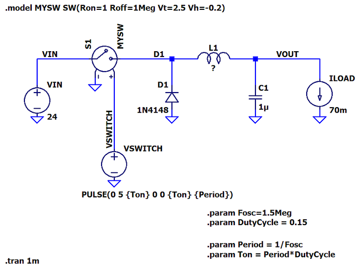
Figure 3. Buck converter power stage simulation schematic with updated switching frequency and duty cycle
I’m using a default value of 1 μF for the capacitor, C1. We’ll discuss capacitor sizing in a future article.
Also, note that I’ve replaced the load resistor with a current source, ILOAD. This ensures that the load current will be 70 mA regardless of the output voltage.
Here is our inductance calculation:
$$L_1=\frac{3.3\ V\times\left(24\ V-3.3\ V\right)}{(0.3\times 70\ \text{ mA}) \times 1.5 \text{ MHz} \times 24\ V}\approx 90.4 \text{ } \mu \text{H}$$
And here is the updated schematic:

Figure 4. Buck converter power stage simulation schematic with inductor value
Simulation of the Buck Converter Power Stage
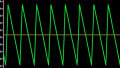
Figure 5 shows the inductor current, load current, and output voltage from simulating our new buck converter.
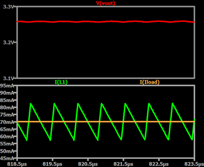
Figure 5. Buck converter output voltage (top-red), inductor current (bottom-green), and load current (bottom-orange)
These results look good, but there are quite a few details yet to examine. We’ll continue this discussion in the next article, and we’ll also consider reasons for using an inductance value that is higher or lower than the initial value that we determined by using the formula.