Facebook
 Google
 GitHub
 Linkedin
Coping with Long-Distance Serial Communication: A New Retimer IC from Texas Instruments
Signal degradation is unavoidable, but various ICs, such as the DS250DF210, can help to restore what has been lost (or eliminate what has been added).
Signal degradation is unavoidable, but various ICs, such as the DS250DF210, can help to restore what has been lost (or eliminate what has been added).
Electrical signals are never really “pure”. Noise is pervasive in every portion of an electronic circuit. Indeed, noise has affected your signal before it ever shows up at an IC’s output pin. And in addition to noise, we have the endless supply of parasitic resistances, capacitances, and inductances that cause a signal to deviate from the idealized version.
However, there is no doubt that certain situations make a particularly generous contribution to signal degradation. The situation that we’re focusing on in this article is long-distance interconnection. Signals are often relatively safe when they’re contained within a well-designed PCB, but interconnection between separate PCBs or separate subsystems is a different story.
- The environment surrounding the cable may be an unfriendly one. Interference is a serious concern when portions of the cable come within close proximity of high-voltage circuitry or wireless transmitters.
- Crosstalk can be a problem, especially when numerous separate signals are densely packed into a cable assembly.
- The wires in the cable are not perfect conductors. A longer cable means more resistance, and more resistance means less voltage available to the circuitry on the other side of the cable.
Lossy Lines
An additional, and rather subtle, source of signal degradation arises when the interconnects—in this context we would refer to them as transmission lines—are “lossy”.

The “lumped-element” model of a transmission line.
A lossy line leads to a form of distortion called dispersion: If the physical characteristics of the line are such that different signal frequencies travel at (significantly) different velocities, the original shape of the signal is lost.
Remember the Fourier transform—anything other than a pure sine wave will contain multiple frequency components, and a frequency-dependent circuit (or transmission line) will affect these frequency components in individualized ways.

Frequency components (red) in a square wave (blue).
The problem with the lossy line is that the propagation velocity depends on the frequency of the signal. Different spectral components of the original signal do not reach the receiver at the same time, and, consequently, the time-domain representation of the received signal is no longer consistent with that of the transmitted signal.
As you might imagine, this effect becomes more pronounced as the length of the transmission line increases. As with any two or more objects moving at different velocities, the difference in arrival time increases in proportion to the total distance traveled.
What Is a Retimer?
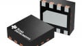
The DS250DF210 from Texas Instruments is described as a “25 Gbps Multi-Rate 2-Channel Retimer”. From this, I can deduce that it is a really, really fast device that does something related to timing and that it does this something for two separate signals.
To be honest, in terms of attempting to assess general functionality, this is one of the most complicated devices I’ve ever encountered. You have to specifically request the full datasheet, which might indicate that the details are so incomprehensible that there’s simply no point in making them readily available to people like me. And even without the details . . . well, let’s just say that you might need to read the part description a few times before you understand what’s going on.

This diagram, from the abbreviated datasheet, is identified as a “simplified schematic". I believe it.
The bottom line here is that the DS250DF210 accepts serial-communication signals that have presumably experienced degradation during their journey from the transmitter to this component, which is not a receiver but more like a repeater station. It locks onto the received signals, does what it can to counteract the degradation, and then outputs the renovated signals. The overall goal is to make long-distance serial-communication links more robust.
I wouldn’t dare to attempt an explanation for how the DS250DF210 actually accomplishes this. The part description mentions a low-jitter FIR filter, an adaptive continuous-time linear equalizer, and an adaptive decision feedback equalizer. I’m sure that I learned about adaptive decision feedback equalizers in one of my first- or second-year EE courses but at this point I don’t recall the details. . . .
Perhaps TI recognized that a few engineers might be intellectually spent by the time they finished browsing the datasheet and, to compensate for this, they made extra efforts to simplify the board design required for this part. The datasheet declares that the DS250DF210 has “minimal need for external components” and the list of features indicates that an external “low-jitter reference clock” is not required and that the part can cope with “minimal supply decoupling”.
Do you have any experience with issues involved in long-distance, high-speed serial communication? Feel free to share your thoughts in a comment.
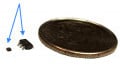
Featured image courtesy of Hardwareonkel (own work) [CC BY-SA 3.0]
Related Content