Facebook
 Google
 GitHub
 Linkedin
MicroPower, MicroSize, Near-Zero Drift, and Low Offset Voltage: A New Op-Amp from Texas Instruments
A new operational amplifier from Texas Instruments offers impressive specifications in a very small package.
A new operational amplifier from Texas Instruments offers impressive specifications in a very small package.
Texas Instruments has released a new low-power, zero-drift operational amplifier, called the OPA2333P. This op-amp is able to simultaneously achieve—thanks to a proprietary auto-calibration technique—an ultra-low offset voltage (10µV maximum) and near-zero drift (0.05 µV/°C maximum) over time and temperature. By the way, based on the description of this part as given in the datasheet, this very-low level of drift seems to qualify as “zero-drift,” though this certainly makes one wonder what exactly the word “zero” means.
If you're not familiar with the term drift, it refers to any change in op-amp performance caused by temperature or ageing. It’s not surprising that temperature would cause an op-amp’s characteristics to vary, but it is perhaps less obvious that ICs change as they get old. Long-term drift is not so important in the context of prototypes and various consumer devices that are frequently replaced, but you never know when you might want something to continue operating for a (very) long time—just think about the Voyager spacecraft!
As can be seen in the figures below, this op-amp exhibits noteworthy offset voltage performance vs. temperature, as well as tight offset-voltage and offset-voltage-drift distributions.
_offset_vs_temperature.jpg)
Figure 1. The OPA2333P’s offset voltage is low and also very stable over the device's operating temperature range (–40°C to 125°C). Plot taken from the datasheet (PDF).
_offset_voltage_production_distribution.jpg)
Figure 2. Minimal offset voltage deviation. Graph taken from the datasheet (PDF).
Single- or Dual-Supply, with Low Current
Although the datasheet states that this device is "optimized" for low-voltage, single-supply operation, it can be used in a dual-supply system, with a range of 1.8 V (±0.9 V) to 5.5 V (±2.75 V). The datasheet doesn’t expand on the term “optimized,” so I’m not sure how exactly the performance is affected by the use of dual supplies. Maybe TI considers these details to be rather unimportant because single-supply configurations are so dominant these days.
With regard to the quiescent current, the electrical characteristics table from the datasheet (section 6.5 on page 5) lists the quiescent current per amplifier (note that this device has two amplifiers) as 17µA typical (25µA maximum) at 25°C and as 28µA maximum from -40°C to 125°C. Using Digi-Key’s part-search functionality, I performed a quick comparison of similar op-amps and discovered that 17µA is actually very low, although there are a few other op-amps with lower IQ values. And for the record, no one is paying me to say that I use Digi-Key; the fact is, their part-search engine is useful for more than just buying parts.
The figure below displays the OPA2333P's quiescent current vs. production distribution and vs. temperature. As you can see, the values exhibit minimal variation.
_quiescent_current.jpg)
Figure 3. Current consumption is stable over temperature and from one part to another. Both plots taken from the datasheet (PDF).
Layout Guidance
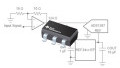
Texas Instruments has provided layout guidelines, both in written form (see Section 10 entitled Layout) and via diagrams. The diagram below includes some excellent general layout suggestions:
- use low-ESR ceramic bypass capacitors,
- minimize trace length in order to reduce errors associated with parasitics,
- keep sensitive analog traces far away from potentially noisy power-supply lines, and
- connect the exposed pad to the negative supply; note that it says “negative “supply,” not “ground”—connecting the exposed pad to ground instead of the negative supply (in a dual-supply system, of course) would be an easy mistake to make.
Additionally, the datasheet includes a package section that provides PCB footprint and stencil recommendations (see pages 29 and 30 of the datasheet). It is especially helpful that they suggest a proper stencil design for the exposed pad.
_layout_example.jpg)
Figure 4. Layout tips, from the datasheet.
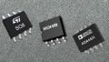
Small Package
As mentioned previously, this micropower op-amp is available in a “microSize” package, specifically, an 8-pin WSON package, which measures 2 × 2 × 0.8 mm (see the figure below). By the way, according to this Wikipedia page, "WSON" stands for very very small outline no lead package. Given this description, I wonder why the acronym isn't "VVSON." Weird.
_IC-Image_dimensions.jpg)
Figure 5. The OPA2333P is available in a 2 × 2 × 0.8 mm package. Taken from the datasheet (PDF).
Have you had a chance to use the OPA2333P in any of your designs? If so, leave a comment and tell us about your experiences.