Facebook
 Google
 GitHub
 Linkedin
Digital (ON/OFF) Hall Effect Devices: Switches and Latches
Learn about the polarity of the B-field, unipolar switches, omnipolar switches, Hall effect latches, and bipolar switches in this technical article.
Hall effect switches and latches are magnetic field comparators. They compare the magnetic flux density, sometimes referred to as the B-field, with some pre-specified thresholds and output the comparison result as a 1-bit digital value. There are four different categories of digital (on/off) Hall sensors: unipolar switches, bipolar switches, omnipolar switches, and latches.
We’ll examine the transfer function of each type in detail. But, before that, I would like to clarify an important concept that will be commonly used in our discussion: the polarity of the magnetic flux density.
How Do We Define the Polarity of the B-field?
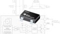
A Hall effect device is directional. It senses only the component of the magnetic flux density that is along its sensitivity axis. Figure 1 shows the sensitivity axis of two common Hall device packages.

Figure 1. Image courtesy of Texas Instruments.
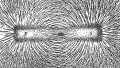
If the magnetic field applied to the device produces a component in the direction of the sensitivity axis, the B-field is assumed to be positive. If the field produces a component in the opposite direction of the sensitivity axis, it is assumed to be negative. Figure 2 shows an example where the magnetic flux density has negative polarity at the sensor location (A).

Figure 2
In the above example, we assume that the device sensitivity axis is in the z-axis direction. Since the magnetic field lines of a magnet go from the north pole to the south pole, the B-field sensed by the device is negative.
There is also a convention regarding the B-field polarity that is commonly used by Hall sensor manufacturers. They consider the magnetic field produced by a magnet south pole as positive and that of the north pole as negative. This is based on the assumption that the branded face of the sensor is toward the magnet. The branded face is the front surface of the sensor where you can find the device part number, etc. Considering the sensitivity axes shown in Figure 1, you can verify that presenting the south pole of the magnet to the branded face of the sensor will create a magnetic field in the direction of the sensitivity axis (positive field). Similarly, a north pole will create a negative magnetic field. If we present the magnet poles to the back side of the sensor package (not the branded face of the package), the above convention won’t be valid anymore!
A final note to finish this discussion: Many Hall devices are one-dimensional and sense the B-field along only one axis of sensitivity (such as those shown in Figure 1). However, there are more sophisticated sensor ICs that employ more than one Hall element to support three axes of sensitivity (a three-dimensional sensor). Now, let’s examine the transfer function of the different types of digital (on/off) Hall devices.
Unipolar Switches
The functionality of a unipolar switch is illustrated in Figure 3.

Figure 3
This device is called a unipolar switch because its switching thresholds (BRP and BOP) are in the positive region of the B-field axis. The output state can only change in response to a south polarity field. A north polarity, or negative, field has no effect on the sensor; explaining the name “unipolar switch”.
Let’s see how the device responds to changes in the magnetic field. Assume that a north polarity field is applied to the sensor and we gradually increase the applied field (make it more positive). For B < BOP, the device is off and the output is logic high. As the applied magnetic field becomes larger (or more positive) than the threshold value BOP, the device turns on and the output switches to the opposite state (logic low). The transfer function for an increasing B-field is shown by the blue curve in the figure.
How does the activated device respond to a decreasing field? For a decreasing magnetic field, the device remains on (logic low) until the applied magnetic field becomes less than BRP. This is shown by the red curve in the above figure. For B < BRP, the device turns off and the output goes to logic high.
Hence, the switching threshold for an increasing magnetic field is different from the switching threshold for a decreasing field. This hysteresis is intentionally designed to have a clean switching at the output. Mechanical vibrations in a Hall effect sensing system as well as electrical and electromagnetic noise can introduce noise into the sensed magnetic field. The B-field noise around the threshold levels can lead to indeterminate, rapidly changing fluctuations at the output of the Hall sensor (Figure 4). These unwanted fluctuations are removed by making the thresholds of the increasing and decreasing fields slightly different.

Figure 4. Without hysteresis, the output can be indeterminate around the threshold.
As we saw above, the operation of a unipolar switch can be described by two different parameters: BOP and BRP. BOP stands for the “magnetic operate point” or simply the “operate point”. This indicates the threshold level for an increasing magnetic field above which the sensor turns on. BRP is the “magnetic release point” or simply the “release point”. It indicates the threshold level for a decreasing magnetic field. For B < BRP, the device is off. The hysteresis is represented by BHYS which is given by:
BHYS = BOP − BRP
We’ll discuss below that a similar notation can be used to describe the operation of the other types of digital Hall devices.
Note that depending on the sensor electronic design, the on and off states of the sensor output might be the opposite of that depicted in Figure 3 (logic low when the device is off and logic high when it is on).
Omnipolar Switches
The transfer function of an omnipolar switch is shown in Figure 5.

Figure 5
An omnipolar switch turns on with either a strong positive field or a strong negative field. As shown in the figure, when the magnitude of the magnetic field becomes larger than BOP (|B| > BOP), the device switches on and the output goes to logic low. When the magnitude of the B-field becomes less than BRP (|B| < BRP), the sensor turns off and the output goes to logic high. The blue curve shows the sensor output when the B-field changes from a large negative value to a large positive value. The red curve shows the output for a decreasing B-field. With an omnipolar switch, the magnitude of the operate point is the same for both positive and negative B-fields. Similarly, the release point magnitude is the same for both south and north polarity fields.
Hall Effect Latches
The transfer function of a Hall effect latch is shown in Figure 6.

Figure 6
A latch device has a positive BOP and a negative BRP. It turns on by a sufficiently large positive field (B > BOP) and turns off at the presence of a sufficiently strong north polarity field (B < BRP). The device hysteresis includes the region around B=0 and ranges from BRP to BOP. We know that the device does not change state in the hysteresis region. Assume that we apply a sufficiently strong positive field to activate the sensor. If we remove this field, the device will sense a magnetic field of B=0. Although no field is applied to the sensor, it will retain its previous state and remain on. It will only change state if we apply a strong field with opposite polarity. When a weak magnetic field is applied to the sensor (BRP < B < BOP), the sensor retains its previously produced output. This explains why this Hall device is called a latch.
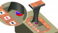
While a unipolar or omnipolar switch can change state as the amplitude of the applied field changes, a latch can sense the polarity of the B-field (provided the applied field has sufficient strength). Latches are usually used with ring magnets in rotary applications for example for detecting the position of a rotating shaft. This is shown in Figure 7.

Figure 7. Image courtesy of Allegro.
As the shaft rotates, the polarity of the sensed magnetic field changes and the sensor turns on/off accordingly. With a latch device, the operate and release points are equal in magnitude but have opposite polarities (BOP ≠ -BRP).
Bipolar Switches
With a bipolar switch, we only know the value of the “maximum” operate point and the “minimum” release point. However, the exact threshold values are not known. Consequently, the exact operation of the device can change on a unit-to-unit basis. Figure 8 shows an example where maximum BOP is about 300 gauss and minimum BRP is about -300 gauss.

Figure 8. Image courtesy of Honeywell.
For “Device 1”, both BOP and BRP are negative. For “Device 3”, both thresholds are positive. Another sample, “Device 2”, has a response similar to that of a latch. It has a positive BOP and negative BRP. Although the transfer function of “Device 2” resembles that of a latch, it should be noted that the operate and release points of a bipolar switch might not be equal in magnitude (BOP - BRP).
As you can see, three different transfer functions are possible even for devices of the same type that are manufactured together in the same lot. According to the “Bipolar Switch Hall-Effect IC Basics'' application note from Allegro, only about 10% of bipolar switches have a transfer function similar to that of “Device 1” and “Device 3”. The rest have a latch-type response. Compared to a latch device, a bipolar switch can offer a narrower hysteresis zone (BHYS = BOP − BRP) and consequently, a higher sensitivity. However, since the operation mode of a bipolar switch can change on a unit-to-unit basis, we need to make sure that the system will function properly for all possible values of BOP and BRP (within the specified range limits).
To see a complete list of my articles, please visit this page.