Facebook
 Google
 GitHub
 Linkedin
Hardware Evaluation for the Cypress S6AE102A/S6AE103A Eval Kit for Energy Harvesting Applications
In this article, we will assess and characterize the hardware of two power management IC development boards from Cypress Semiconductor, designed for energy-harvesting applications.
In this article, we will assess and characterize the hardware of two power management IC development boards from Cypress Semiconductor, designed for energy-harvesting applications.
The S6AE102A and S6AE103A Power Management Integrated Circuit (PMIC) devices allow designers to power their IoT sensor designs using light that is already present in the operational environment. These PMICs are able to harvest energy indoors with appropriately chosen solar cells. This technical article explores the CYALKIT-EO4 Evaluation Kit, which supports the S6AE102A and S6AE103A PMICs.

The S6AE102A (top left) and S6AE103A (top right). Also pictured (bottom row, left to right) are the included sensor board (top and bottom views) and solar module.
When photons strike a solar cell, their energy affects electrons in a way that leads to electric current (if a closed circuit is present). Unfortunately, the efficiency of the conversion process from light to electricity is relatively low. When solar cells are used indoors, limited available light combined with the inefficiency of photovoltaic devices makes solar energy harvesting inadequate in many use cases.
However, the S6AE10xA line of energy harvesting ICs consume incredibly small amounts of current (~280 nA) and can store energy from solar cells to run low-power sensor solutions. This allows designers to create wireless sensors that never need batteries. For example, a window-alarm might combine a low-power sensor, such as the BMA400 accelerometer (<4 µA), and a BLE5 SoC, such as TI’s BLE5 CC2640R2F128 SOC (1.1 µA sense, 9.1 mA during burst transmit).
Monitoring of the accelerometer would require only ~15 µW if done continuously (much less if sampled at 5 Hz), then when movement is detected, a short burst of energy is required to transmit for a few milliseconds. Thus, the rate of energy generation could exceed the rate of energy consumption. (See this document for generation estimates.)
Basics of Operation
.jpg)
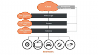
Typical architecture for energy-harvesting embedded devices that are built around the S6AE101A/2A/3A PMICs.
As soon as enough light falls on a solar cell to provide current to the device, the S6AE101xA PMIC activates and delivers energy to the system. If the system is not active, or additional energy is available at the input, the device stores the energy in a capacitor for later use.
An internally switched power block can deliver the energy from a battery or solar cell to capacitors or an adjustable output voltage LDO.
.jpg)
The power block inside the S6AE102A/S6AE103A device controls the state of the connections in the power inputs and outputs. Image from Cypress datasheet.
.jpg)
Block diagram of the S6AE102A/S6AE103A PMIC from Cypress Semiconductor Datasheet.
To learn more about these devices, AAC purchased the CYALKIT-E04, which contains evaluation boards for the S6AE102A/S6AE103A.
CYALKIT-EO4
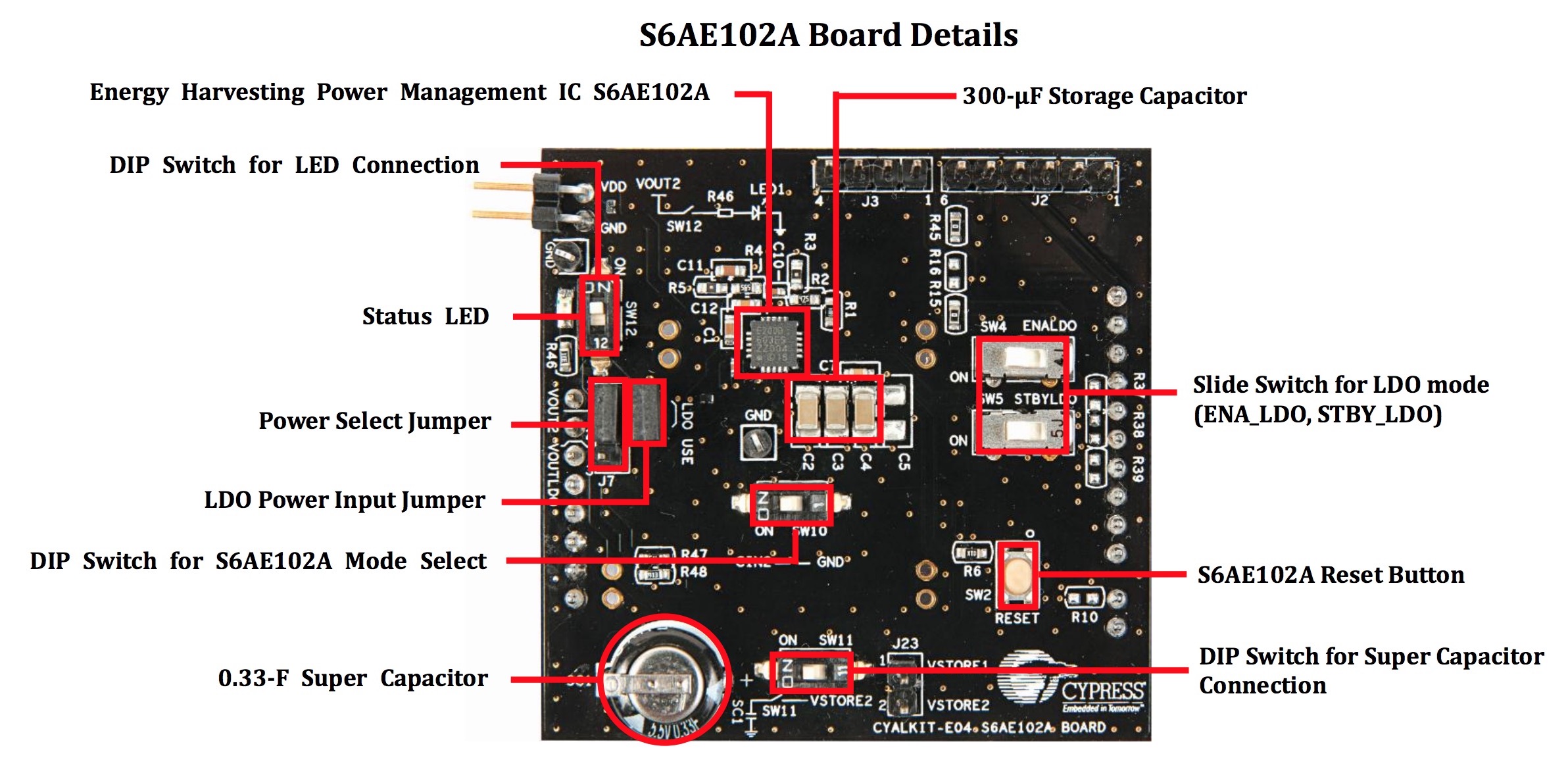
S6AE102A EVM board. Click to enlarge.
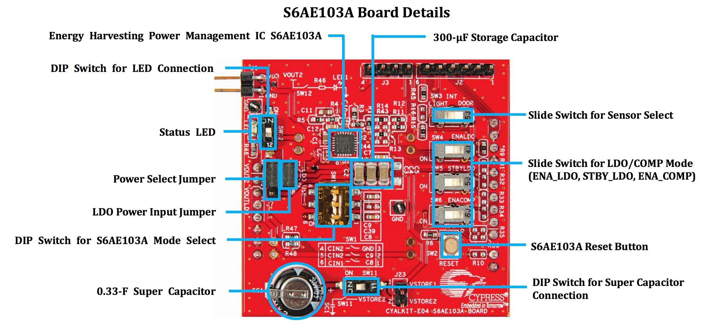
S6AE103A EVM board. Click to enlarge. Images from the S6AE102A and S6AE103A Evaluation Kit Guide.
These boards offer similar functionality and have the capability of connecting to the CY8CKIT-042-BLE Bluetooth Low Energy Kit as well as devices with Arduino-compatible headers.
Both PMICs have similar features; however, the S6AE103A has an extra four pins that add an additional two timers and one comparator to the design.
Testing the Kits
To learn more about the devices, I connected the S6AE103A to the solar cell provided in the kit and recorded the potential difference at test points VStore1 and VStore 2 with the Tektronix MDO3104 oscilloscope and TPP1000 probes.
For this example, SW12 was in the off position (turning off the charging indicator LED) and SW11 was in the on position (charging the onboard 0.33 F supercapacitor). Primary illumination was provided by an LED desk lamp located 30 cm above the solar cell. Secondary illumination came from a computer monitor (facing away from the solar cell) and an incandescent room light (over 2 m away).
.png)
This image shows the charging cycle time before (left eight divisions) and after (right two divisions) the LED desk lamp was turned on. As the lamp’s knob was turned to full brightness, the charge period further decreased (shown in images below). This indicates that the lamp, even at its lowest setting, was the primary source of energy.
I used a 200 s/div time-scale setting to show a large portion of the supercapacitor charge cycle. The Tektronix MDO3104 is capable of 1000 s/div; that would have illustrated much more of the charge cycle, but it would take 2 hours and 45 minutes to fill the oscilloscope screen. Even at 200 s/div you need to wait a long time; it took 33 minutes to record what is shown below.
Channel 1 (yellow) shows the voltage at the VStore1 test point, and Channel 2 (blue) shows the voltage at the VStore2 test point (i.e., the supercapacitor voltage).
.png)
Shown above is a 33-minute recording of the supercapacitor charging indoors at night via a desk lamp (Channel 2, blue). See below for better representations of the voltage at the VStore1 test point.
The Charging Circuit
Energy from the solar cell is initially transferred to the capacitor connected to the VStore1 pin. When an upper voltage threshold is detected, energy is transferred from the small capacitor connected to the VStore1 pin to the supercapacitor connected to the VStore2 pin.
As the VStore1 capacitor voltage decreases due to charging of the VStore2 capacitor, it will eventually reach a lower threshold voltage and cease charging the supercapacitor until the upper threshold is reached again.
.png)
The voltage across the VStore1 capacitor (yellow) cycles between upper and lower voltages. At the upper voltage threshold, charging of the VStore2 supercapacitor begins. At the lower voltage threshold, charging of the VStore2 supercapacitor ceases.
.png)
Summary
The Cypress S6AE10xA power management ICs help you to design sensors and other low-power embedded devices that can be powered from ambient light. This could be an effective and fairly simple way to ensure that your device can operate longer than current battery technology allows.