 Facebook
 Google
 GitHub
 Linkedin
Galvanic Isolation: Purpose and Methodologies
Galvanic isolation is a way to isolate functional sections of electrical systems to prevent current flow. A brief explanation of differing methods to create galvanic isolation.
Introduction
Galvanic isolation, generally just referred to as isolation, is the convention used whereby individual parts of the electrical system may possess different ground potentials. The two most common reasons for creating isolation are safety from fault conditions in industrial grade products and where wired communication between devices is needed but each device regulates its own power.
Methods for Power Isolation
Transformers
The most common form of isolation is the use of a transformer. When designing a power regulation circuit where isolation is required, the isolation portion of the design is coupled with the need to step up/step down a voltage rail and is not recognized as an individual portion of the system. In the event that an entire electrical system needs to be isolated (Example: Many automotive validation tests requires power sources be isolated from AC mains) a 1:1 transformer can be placed in series with the system to create the required isolation.
![]()
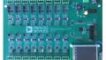
Figure 1: An Assortment of SMD Transformers
Capacitors
A less common method of creating isolation is the use of series capacitors. Due to the permissibility of AC signals through capacitors, this can be an effective method of isolating portions of the electrical system from AC mains. This method is less robust than the transformer method, as a transformer's failure mode is an open while one of a capacitor's failure modes is a short. One of the purposes of creating galvanic isolation from the AC mains is such that in the event of a failure the user is safe from a functionally limitless current source.

Figure 2: Example of Capacitors being used to Create Isolation
Methods for Signal Isolation
Opto-isolators
When a signal is required to pass between 2 ground potentials, an opto-isolator is a popular solution. An opto-isolator is a photoresponsive transistor that turns ON when its internal LED is energized. The light emitted from the internal LED is the signal path and thus does not violate the isolation barrier between ground potentials.

Figure 3: Schematic of a Typical Opto-Isolator
Hall Effect Sensor
Another method of passing information between electrical systems with separate ground potentials is the use of a Hall effect sensor. A Hall effect Sensor detects inductance non-invasively and does not require direct contact with the signal in question and does not violate the isolation barrier. The most common use of passing inductive information across varying ground potentials is in current sensing probes.

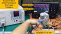
Figure 4: A Current Probe being used to Measure Current through a Conductor
Conclusion
Galvanic isolation is the separation of electrical systems/subsystems by which non direct current can flow and may possess different ground potentials. Isolation can be divided into to main categories: power and signal. There are several methods to achieving isolation and depending on the design requirements some methods may be preferential to others.
Practical Example:
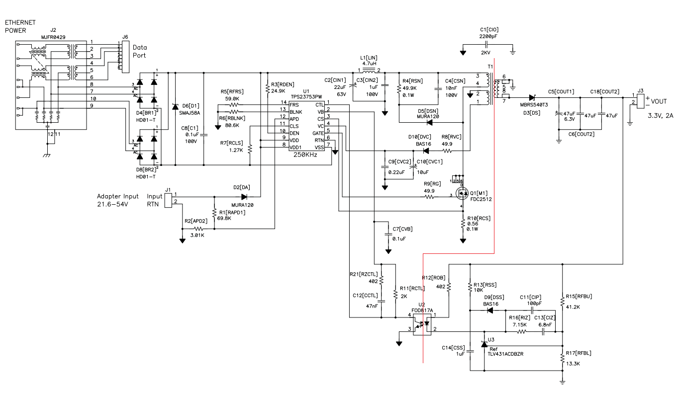
Figure 5: Schematic of a Power over Ethernet Design based on TPS23753PW Controller
In the circuit above, several transformers and an opto-isolator are implemented to create a switching power supply that is used in power over Ethernet PD (Powered Device) devices. The connector J2 has internal magnetics that isolate the entire system from the PoE source. T1 and U2 isolate the switching power supply (The left side of the red line) from the regulated 3.3V output (the right side of the red line).
Related Content


So the purpose of the two isolators on the schematic are to create redundancy between for the 3.3v signal going to J3-1?