 Facebook
 Google
 GitHub
 Linkedin
Isolation and Gain: A New Isolation Amplifier from Texas Instruments Suited for Current Sensing
Amplifiers such as the AMC1301-Q1 are a convenient solution for isolated current and voltage measurements.
Amplifiers such as the AMC1301-Q1 are a convenient solution for isolated current and voltage measurements.
Isolation, more specifically galvanic isolation, is a topic that comes up from time to time. In my experience, it’s somewhat unfamiliar to many folks because certain types of projects never require it. In contrast, engineers working with industrial systems might discuss isolation on an almost daily basis. It’s simply a matter of the design situations that you normally deal with. Consumer electronics, embedded systems, low-voltage sensor circuits, etc.—these usually adhere to the “many voltages, one ground” paradigm.
Isolation comes into play when we want to protect one ground from another, or when one portion of a circuit or system is incompatible with the voltages present in another portion. There are various ways to achieve galvanic isolation. Optocouplers are a well-known option, but you can also use magnetic couplers.
A somewhat distinct approach is the isolated (or isolation) amplifier. These components are not fundamentally different from standalone isolators because they rely on the same technology for the isolation part of the circuit (there are only so many feasible ways to transfer electrical information without using electric current). What makes them interesting is the integration.
The Block Diagram

Diagram taken from the datasheet.
The AMC1301-Q1 from Texas Instruments is a fixed-gain isolated amplifier. When you look at the block diagram, you see neither optical circuitry nor magnetic circuitry, even though I just referred to the fact that isolators are based on optical or magnetic coupling. Instead, all you see are ordinary capacitors.
Capacitive Coupling
It’s easy to forget that capacitors can provide isolation, simply because we don’t typically use them for that purpose. However, they don’t provide isolation in the way that an optocoupler does—an optocoupler blocks all frequencies, whereas a capacitor is an open circuit only at DC. But this is a non-issue if all you’re trying to do is protect one subcircuit from the non-varying (or very-slowly-varying) common-mode voltages in another subcircuit. And this is indeed a standard situation in which isolation of some kind is called for.
The catch, of course, is that you can’t transfer low-frequency information by means of capacitive coupling. This is true for magnetic coupling, as well. Optical coupling theoretically allows for low-frequency analog data transfer— a certain voltage can be represented by steady illumination at a certain intensity. But, as far as I know, optocouplers are not used this way in practice; to achieve adequate accuracy, modulation is required.

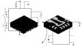
The AMC1301-Q1 gives you 1500 V of steady-state isolation and is AEC-Q100 qualified. Image courtesy of Texas Instruments.
As you can see in the block diagram, the AMC1301-Q1 uses delta-sigma modulation, which converts low-frequency signals to a high-frequency bit stream that can successfully cross the capacitive isolation barrier. Then, synchronization and filtering are performed on the other side of the amplifier so that the analog output signal reproduces the analog input signal multiplied by the fixed gain (which for the AMC1301-Q1 happens to be 8.2 V/V).
Applications
I wouldn’t go so far as to describe the AMC1301-Q1 as a general-purpose amplifier. In other words, I wouldn’t use it as a drop-in isolated replacement for your favorite op-amp. Some quality will inevitably be lost in the process of modulating and demodulating the input signal, and the current consumption is rather high compared to modern low-power amplifiers. And in any event, TI is not marketing this part as an isolated version of a general-purpose amplifier. It is clearly optimized for current-sensing applications and other similar uses.
In this way the AMC1301-Q1 is addressing a common design challenge: a low-voltage sensor circuit needs to measure a current or voltage present in a high-voltage or high-current portion of the system. The sensor needs to be protected from noise and/or high common-mode voltages, and thus an isolated amplifier is called for. The following circuit gives you an example of an isolated current-sensing application; the shunt resistor creates the input voltage, and the output is fed to an ADC.
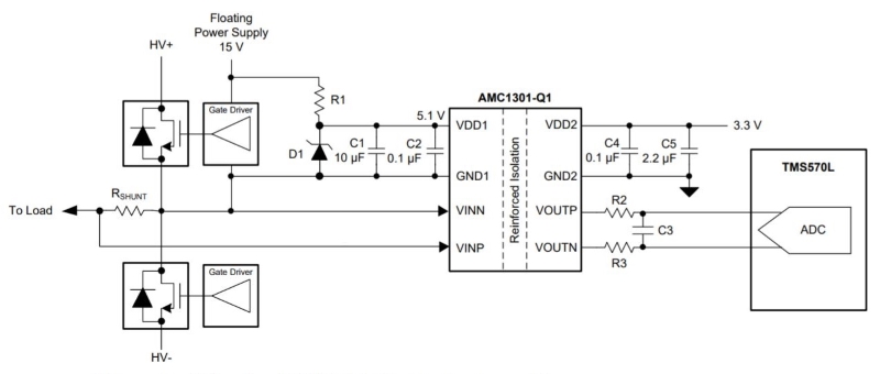
Diagram taken from the datasheet.
Note how this schematic suggests the old-fashioned approach to voltage regulation—VDD for the high-voltage side is generated via the resistor-plus-Zener-diode method. Also, keep in mind that the differential input voltage is limited to ±250 mV (it actually can go a bit higher than that but with loss of linearity).
If current sensing isn’t your thing and you’d rather keep an eye on voltage, here’s an example circuit for voltage sensing:

Diagram taken from the datasheet.
Do you have any experience with isolation amplifiers? Let us know in the comments.
Related Content


It has been my keen interest to detect flow of charge carriers before an isolation method could be tailored to suit the need. Let’s use an example of a Ni-cad multi cell battery with a metal painted casing which are often used on aircraft’s. In this case, due to the nature of the construction of this battery the manufacturer will specify a case lekage test usually in the realm of milli amps before the battery could be certified as airworthy.
I have done some preliminary testing in the realm of micro amps and surprisingly the initial data is interesting as far as the insulation material degradation and impurities buildup on surface area of the overall battery.
It is in fact a circuit that is either encourages the charge carrier flow or discourages it over time¡
nice informative article