 Facebook
 Google
 GitHub
 Linkedin
Delta-Sigma ADC
One of the more advanced ADC technologies is the so-called delta-sigma, or ΔΣ (using the proper Greek letter notation). In mathematics and physics, the capital Greek letter delta (Δ) represents difference or change, while the capital letter sigma (Σ) represents summation: the adding of multiple terms together. Sometimes this converter is referred to by the same Greek letters in reverse order: sigma-delta, or ΣΔ.
In a ΔΣ converter, the analog input voltage signal is connected to the input of an integrator, producing a voltage rate-of-change, or slope, at the output corresponding to input magnitude. This ramping voltage is then compared against ground potential (0 volts) by a comparator.
The comparator acts as a sort of 1-bit ADC, producing 1 bit of output (“high” or “low”) depending on whether the integrator output is positive or negative. The comparator’s output is then latched through a D-type flip-flop clocked at a high frequency, and fed back to another input channel on the integrator, to drive the integrator in the direction of a 0 volt output. The basic circuit looks like this:
Schematic Diagram
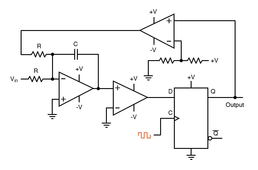
The leftmost op-amp is the (summing) integrator. The next op-amp the integrator feeds into is the comparator, or 1-bit ADC. Next comes the D-type flip-flop, which latches the comparator’s output at every clock pulse, sending either a “high” or “low” signal to the next comparator at the top of the circuit.
This final comparator is necessary to convert the single-polarity 0V / 5V logic level output voltage of the flip-flop into a +V / -V voltage signal to be fed back to the integrator. If the integrator output is positive, the first comparator will output a “high” signal to the D input of the flip-flop.
At the next clock pulse, this “high” signal will be output from the Q line into the noninverting input of the last comparator. This last comparator, seeing an input voltage greater than the threshold voltage of 1/2 +V, saturates in a positive direction, sending a full +V signal to the other input of the integrator.
This +V feedback signal tends to drive the integrator output in a negative direction. If that output voltage ever becomes negative, the feedback loop will send a corrective signal (-V) back around to the top input of the integrator to drive it in a positive direction.
This is the delta-sigma concept in action: the first comparator senses a difference (Δ) between the integrator output and zero volts. The integrator sums (Σ) the comparator’s output with the analog input signal.
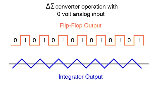
Functionally, this results in a serial stream of bits output by the flip-flop. If the analog input is zero volts, the integrator will have no tendency to ramp either positive or negative, except in response to the feedback voltage.
In this scenario, the flip-flop output will continually oscillate between “high” and “low,” as the feedback system “hunts” back and forth, trying to maintain the integrator output at zero volts:
Output Waveforms
If, however, we apply a negative analog input voltage, the integrator will have a tendency to ramp its output in a positive direction. Feedback can only add to the integrator’s ramping by a fixed voltage over a fixed time, and so the bit stream output by the flip-flop will not be quite the same:
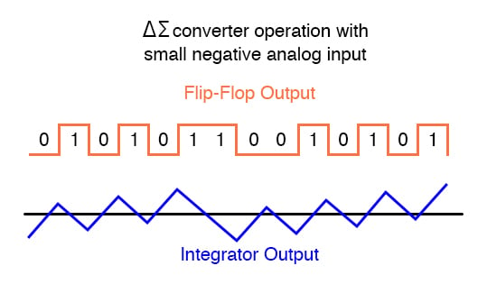
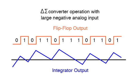
By applying a larger (negative) analog input signal to the integrator, we force its output to ramp more steeply in a positive direction. Thus, the feedback system has to output more 1’s than before to bring the integrator output back to zero volts:
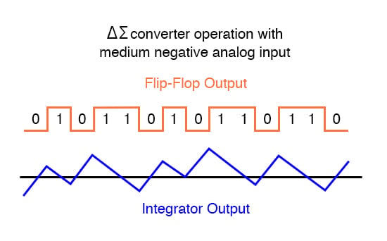
As the analog input signal increases in magnitude, so does the occurrence of 1’s in the digital output of the flip-flop:
A parallel binary number output is obtained from this circuit by averaging the serial stream of bits together. For example, a counter circuit could be designed to collect the total number of 1’s output by the flip-flop in a given number of clock pulses. This count would then be indicative of the analog input voltage.
Variations on this theme exist, employing multiple integrator stages and/or comparator circuits outputting more than 1 bit, but one concept common to all ΔΣ converters is that of oversampling. Oversampling is when multiple samples of an analog signal are taken by an ADC (in this case, a 1-bit ADC), and those digitized samples are averaged.
The end result is an effective increase in the number of bits resolved from the signal. In other words, an oversampled 1-bit ADC can do the same job as an 8-bit ADC with one-time sampling, albeit at a slower rate.
RELATED WORKSHEET:


