Facebook
 Google
 GitHub
 Linkedin
Practical Considerations of ADC Circuits
Perhaps the most important consideration of an ADC is its resolution. Resolution is the number of binary bits output by the converter. Because ADC circuits take in an analog signal, which is continuously variable, and resolve it into one of many discrete steps, it is important to know how many of these steps there are in total.
For example, an ADC with a 10-bit output can represent up to 1024 (210) unique conditions of signal measurement. Over the range of measurement from 0% to 100%, there will be exactly 1024 unique binary numbers output by the converter (from 0000000000 to 1111111111, inclusive).
An 11-bit ADC will have twice as many states to its output (2048, or 211), representing twice as many unique conditions of signal measurement between 0% and 100%.
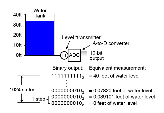
Resolution is very important in data acquisition systems (circuits designed to interpret and record physical measurements in electronic form). Suppose we were measuring the height of water in a 40-foot tall storage tank using an instrument with a 10-bit ADC.
0 feet of water in the tank corresponds to 0% of measurement, while 40 feet of water in the tank corresponds to 100% of measurement. Because the ADC is fixed at 10 bits of binary data output, it will interpret any given tank level as one out of 1024 possible states.
To determine how much physical water level will be represented in each step of the ADC, we need to divide the 40 feet of measurement span by the number of steps in the 0-to-1024 range of possibilities, which is 1023 (one less than 1024). Doing this, we obtain a figure of 0.039101 feet per step.
This equates to 0.46921 inches per step, a little less than half an inch of water level represented for every binary count of the ADC.
This step value of 0.039101 feet (0.46921 inches) represents the smallest amount of tank level change detectable by the instrument. Admittedly, this is a small amount, less than 0.1% of the overall measurement span of 40 feet.
However, for some applications it may not be fine enough. Suppose we needed this instrument to be able to indicate tank level changes down to one-tenth of an inch. In order to achieve this degree of resolution and still maintain a measurement span of 40 feet, we would need an instrument with more than ten ADC bits.
To determine how many ADC bits are necessary, we need to first determine how many 1/10 inch steps there are in 40 feet. The answer to this is 40/(0.1/12), or 4800 1/10 inch steps in 40 feet. Thus, we need enough bits to provide at least 4800 discrete steps in a binary counting sequence.
10 bits gave us 1023 steps, and we knew this by calculating 2 to the power of 10 (210 = 1024) and then subtracting one.
Following the same mathematical procedure, 211-1 = 2047, 212-1 = 4095, and 213-1 = 8191. 12 bits falls shy of the amount needed for 4800 steps, while 13 bits is more than enough. Therefore, we need an instrument with at least 13 bits of resolution.
Another important consideration of ADC circuitry is its sample frequency, or conversion rate.
This is simply the speed at which the converter outputs a new binary number. Like resolution, this consideration is linked to the specific application of the ADC. If the converter is being used to measure slow-changing signals such as level in a water storage tank, it could probably have a very slow sample frequency and still perform adequately.
Conversely, if it is being used to digitize an audio frequency signal cycling at several thousand times per second, the converter needs to be considerably faster. Consider the following illustration of ADC conversion rate versus signal type, typical of a successive-approximation ADC with regular sample intervals:
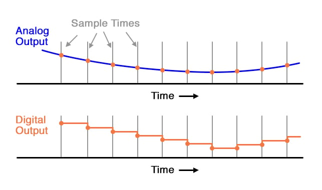
Here, for this slow-changing signal, the sample rate is more than adequate to capture its general trend. But consider this example with the same sample time:
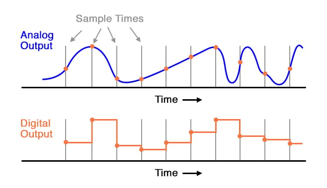
When the sample period is too long (too slow), substantial details of the analog signal will be missed. Notice how, especially in the latter portions of the analog signal, the digital output utterly fails to reproduce the true shape.
Even in the first section of the analog waveform, the digital reproduction deviates substantially from the true shape of the wave. It is imperative that an ADC’s sample time is fast enough to capture essential changes in the analog waveform.
In data acquisition terminology, the highest-frequency waveform that an ADC can theoretically capture is the so-called Nyquist frequency, equal to one-half of the ADC’s sample frequency. Therefore, if an ADC circuit has a sample frequency of 5000 Hz, the highest-frequency waveform it can successfully resolve will be the Nyquist frequency of 2500 Hz.
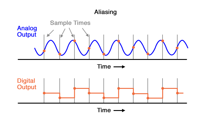
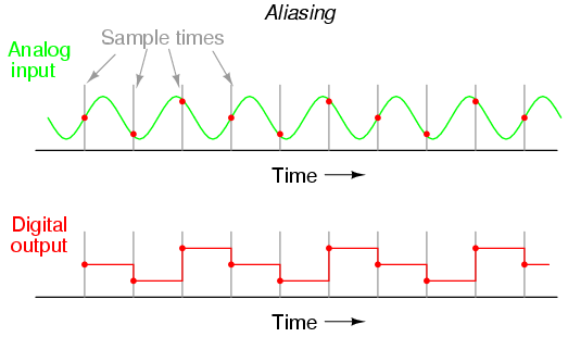
If an ADC is subjected to an analog input signal whose frequency exceeds the Nyquist frequency for that ADC, the converter will output a digitized signal of falsely low frequency. This phenomenon is known as aliasing. Observe the following illustration to see how aliasing occurs:
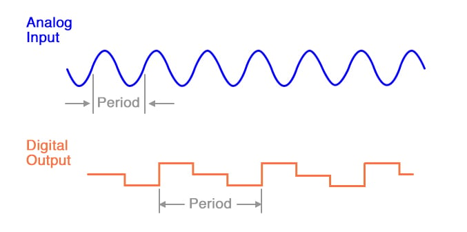
Note how the period of the output waveform is much longer (slower) than that of the input waveform, and how the two waveform shapes aren’t even similar:
It should be understood that the Nyquist frequency is an absolute maximum frequency limit for an ADC, and does not represent the highest practical frequency measurable. To be safe, one shouldn’t expect an ADC to successfully resolve any frequency greater than one-fifth to one-tenth of its sample frequency.
A practical means of preventing aliasing is to place a low-pass filter before the input of the ADC, to block any signal frequencies greater than the practical limit. This way, the ADC circuitry will be prevented from seeing any excessive frequencies and thus will not try to digitize them.
It is generally considered better that such frequencies go unconverted than to have them be “aliased” and appear in the output as false signals.
Yet another measure of ADC performance is something called step recovery. This is a measure of how quickly an ADC changes its output to match a large, sudden change in the analog input. In some converter technologies especially, step recovery is a serious limitation.
One example is the tracking converter, which has a typically fast update period but a disproportionately slow step recovery. An ideal ADC has a great many bits for very fine resolution, samples at lightning-fast speeds, and recovers from steps instantly. It also, unfortunately, doesn’t exist in the real world.
Of course, any of these traits may be improved through additional circuit complexity, either in terms of increased component count and/or special circuit designs made to run at higher clock speeds.
Different ADC technologies, though, have different strengths. Here is a summary of them ranked from best to worst:
- Resolution/complexity ratio: Single-slope integrating, dual-slope integrating, counter, tracking, successive approximation, flash.
- Speed: Flash, tracking, successive approximation, single-slope integrating & counter, dual-slope integrating.
- Step recovery: Flash, successive-approximation, single-slope integrating & counter, dual-slope integrating, tracking. Please bear in mind that the rankings of these different ADC technologies depend on other factors.
For instance, how an ADC rates on step recovery depends on the nature of the step change. A tracking ADC is equally slow to respond to all step changes, whereas a single-slope or counter ADC will register a high-to-low step change quicker than a low-to-high step change.
Successive-approximation ADCs are almost equally fast at resolving any analog signal, but a tracking ADC will consistently beat a successive-approximation ADC if the signal is changing slower than one resolution step per clock pulse.
I ranked integrating converters as having a greater resolution/complexity ratio than counter converters, but this assumes that precision analog integrator circuits are less complex to design and manufacture than precision DACs required within counter-based converters. Others may not agree with this assumption.