Facebook
 Google
 GitHub
 Linkedin
Counters
Video Lectures created by Tim Feiegenbaum at North Seattle Community College.
Hey, we are continuing in 15-3 and we are looking at the subject of counters and as is a Flip Flop that's configured to toggle on every clock pulse, it's a one bit counter. If multiple Flip Flops connected together, a counter of any length can be built. There are two general classes of counters; we have asynchronous variety. Clock pulses arrive at the Flip Flop at different times. Then there are synchronous when the clock pulses arrive at the Flip Flop at the same time - meaning that the clock pulses simultaneously - fed into all of the Flip Flops at the same instant.
Here we have a JK Flip Flop and one of the essential points of doing counters is the ability to divide by two, so a Flip Flop will effectively divide the incoming frequency by two. Let's look at how that occurs.
First of all, the JK Flip Flop, if we have the J and the K inputs both set to one ... then if you will recall, this will cause it to toggle, change the output, changing with every clock input. Here we have an external clock and we would be refeeding to a pulse to the ... then this would be the clock input. You will notice the little greater than symbol that indicates that it's going to be clocking on positive going clock pulses. Here we have a clock pulse coming in; we'll just start it right here. Here we have the incoming positive edge and what we will know here is on the incoming positive edge of the output goes to a one. That would be a one and a zero and obviously the ? would be zero.
Then as the cycle progresses, it goes negative. Nothing happens as it goes negative. Then as it goes positive, again the output of this Flip Flop changes state. Now it goes to zero and one and then we go on and the next positive edge, again it changes states here. Then we go to one zero and on every positive edge, it's going to change states. We have a result in the output of a ... and this is the result in output right here, but of note is that you see this frequency coming in and you see this frequency coming out. What can be observed is that this frequency is twice this frequency. A Flip Flop coming in that is configured like this will toggle and the output will be half of the input frequency.
Now we have a counter and this counter is going to be a three-bit counter. You will notice we have Flip Flop A, B, and C. This is actually figure 1526 in your textbook and we have a circuit that we are going to talk about later. In fact, it is this circuit but we will actually see the simulation later in this presentation. This is the actual outputs of this device. Now, first of all, I want to bring your attention to this concept again of dividing by two. We are going to be looking at this outputs. We haven't defined what they are. This is the output of A, this is B and that coincides with the outputs A, B, and C of this Flip Flop. You'll know here we have the incoming clock frequency. The output of C here will be, which is what we just previously looked at ... would be right here.
You will notice that it is half the frequency of the clock frequency. Then if you compare C to B, what you will observe is that B is actually half of C. Likewise if we go up to B and compare it to A, we'll note that A is half of B. If we were to look at this and assign weights to it, A would be ... we have one cycle and then B we would have two cycles and then C, there would be four and then the clock will be A. Recall when we did our binary weighting and we set 1, 2, 4, A, 16, 32 and so one and so forth. This was the way that we weighted binary values. If we said that we had ... since this is three bits, if we had a one zero one, we said that that would be 4+1 and we said that equals five. This frequency division sets up a scenario where we are going to be able to actually count.
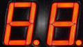
Let's take a closer look at this particular waveform and if we will note here ... we notice that at this point, this is a low, a low and a low. That would equate to zero and notice we have a counter here. This is counting from zero up to seven and that would be right here. Then the next one, we have a zero zero and one and that would be the one which is right here. Then we go one. Here we have a zero one and zero that would equate to two. Let's see. Then we have a zero one one that would be three and one zero zero that would be a four, one zero one that would be a five and a one one zero that would be six and then probably one one one that would be seven. Then it resets and goes zero zero zero and then it repeats this process. That is essentially what we do with a counter and it utilizes this divide function and we see the results here where we are actually ... and you can see the pulses that will indicate this different numbers.
Now we do want to look at how is it that this actually works, because there is a specific methodology that makes that process happens. On this particular screen, I've taken the same schematic. I've made it a little bit larger and then we also have taken the timing sequence and enlarged it a little bit as well. Let's review a little bit here, let's see here.
We had again .. here this is A, B, and C and these corresponds to Flip Flops, the output of Flip Flop A, B and C. Our counting, let's see, we would have ... this would be starting at zero and we would count up through seven. Now let's look at the initial state of the circuit. Notice that we have the clock pulse coming in right here and notice that the clock pulse ... this is a synchronous counter. What that means is that clock pulses simultaneously fed into all of the Flip Flops at the same time. It would be clocking them depending on what is at the input of the Flip-Flop. Now recall that in this particular case, there will either be zeros on the inputs of the J and the K or there will be ones that are the only two options we will have in this circuit.
Remember if there are ones on the inputs, then it would toggle. If it is zeros, they would just stay in whatever condition they were in and they will not change. Now note we have a positive voltage here and so that will put a high here and a high here. What will happen is that Flip Flop C, which I'll put QC right here, will toggle on every input, every clock pulse that comes in. This has little bubbles here. You will notice here we have the negative edges occurring here, here, here and all the way across. On every negative edge, this one is going to count and this is effectively our one, remember when we had the 1, 2 and 4 in our weighted position in binary. This is effectively our one's digit, so it would be expected that it is going to toggle on every single count that our two and our four will not.
In the initial state, when we are at zero zero zero, we are going to ... let's look at the state of our various Flip Flops. This has 1 and 1 on it. It will toggle from zero zero zero. It will toggle to one on the first clock because it has the appropriate inputs on J and K. Now let's look at the inputs on Flip Flop B and Flip Flop A. Now notice the output of C comes over here and it feeds into JD and KB which is Flip Flop B. Now recall initially we were at zero zero zero. Initially, this is feeding a zero here. On the first clock pulse, this will not change because there is nothing there. There is no voltage, there's a zero here, so it will not change states, so B won't change.
Now let's consider A. Now when we have at zero zero, let's look at the ?-0's position. ?-0s they should all be high, one one and one. Now, what feeds into the Flip Flop A here, the J and K inputs are fed by this [inaudible 00:10:59]. Now notice we have the ?B-0 comes up here, it has a one on it and ?C-0 also comes up and there is a one here – so a one and a one going into this, so that's going to result into a zero. There will be a low on both of these inputs and there will be a low on both of these. Now, this represents the initial states.
When that first clock pulse comes in right here, it would actually be right here and it will cause this Flip Flop to trigger and it will place a one on the output. Probably just indicated here, it places a one at QC's output and we have the count of one and these two will remain at zero. Now at one, notice that this output goes over to J and K of B. That is going to change these two; we're going to have a one here now. Here we have one and then this was our first clock pulse right here. Then we come here and here is our second edge.
Now our second edge is going to do something interesting. Remember this one toggles on everyone, so this output is going to change to zero. Recall when we had one, there was the one setting here. There was a one on J and B at the time of this edge. The output of B toggles to one, okay. Here we have the toggle action here and so here we have a one and a zero and so that reflects the output of B and C, so now we have the count of two.
Now at this point, we are at one one and zero. We're at two. Notice this zero stayed over here and now there is a low here. Now that is significant because when we count to three which is going to be right here - when we go to zero one one - this has to remain the same. We are at one zero. Now we want to go to one one. Well, this will stay at one because this zero here has stayed here when the clock pulse comes in; it won't change states because if there are zeros here, it just remains as it was. That will give us zero one one which gives us three.
At this point, we are at one and one; we had counted to three, profound huh? Zero one one is our current output. Now on the next clock pulse, this one is always going to change and recall we have a one going over here, so there's a one here. In the next clock pulse, it will toggle from one to zero, okay. The count that we are going to, is going to be one zero zero which is four. We are three now so we can see that these two will change. This one has to go to one.
Now let's look at the conditions that will make this go to one. First of all, this is a one and this is a one so that means that we have a zero here and a zero here. If the ?B and the ?C are zeros, if they come up here, notice what is going to happen. We have a zero and a zero, that will enable this so then we will have a high right here. That will put a high on QA-0. What that will do on the next clock pulse, we know that this will toggle to zero and zero, this will toggle to one. That will give us four which is right here, which is one zero zero.
Now we are at one zero zero and since we are at one zero zero, we need to note something about this gate. When we toggle to one zero zero, that changed this to a high and this to a high, both ?B and ?C went high. That changes both of those to one which makes this zero. What will happen is on the next few counts, this is simply going to remain as a one, because the only time that this digit will change, is when both of this are high. Through the next couple of counts, these are going to go to one and then two and then three and then it will switch again. Because we are at count four, notice for count five, six and seven this has to remain high.
We are at count number four and there is a zero going over here. To go to five, we need to go to one zero one. Now in order to do that, this has to remain the same and since this is a zero from QC, this will not toggle, but this will always toggle because of the fact that we have the ones here. That will give us five, so that would be one zero one.
The next one, let's see where we are at. One zero one - then the one from QC goes over to our J and our K inputs here on the next pulse. QB will toggle because of that, QC will also toggle but they're just going to Flip Flop. We are at one zero one. Then we will be at one one zero. Again we are at one, now we are at ... Let's see, we have to find a place to write. I guess we'll write then down here. We are one one zero that gives us our count of six. Since we are at zero here, on the next count, this will not toggle because there are zeros on the B. C will always toggle, so then we will have one one one.
The next one is a critical count because we have to go from one and effectively re-reset to zero. Now the way this is going to occur, notice this one will always toggle, so it will go to zero. Notice we have the one going over here to this, so this one is going to toggle. Since we have the one here and the one here on the B and C outputs - the ?B and the ?C - again they are at that zero state that is the only state that causes this to be enabled so we have a one here. We have ones on all of the JK inputs and each of the states of the JKs are ones. On the next clock pulse, we will go to zero.
That is the basic theory of how a counter works. This is a synchronous counter. Now this particular image right here, this is a simulation of that particular circuit. Now you'll notice there is a lot more wires in it because we've got to the clears and sets have to be there and then we have added these little light bulbs for illumination. Now what you can do and I encourage you to do this. This is going to be a circuit, 1526 is to do the simulation and when you turn this one, you're going to see these lights illuminate and these lights will represent the counters.
In fact when we started with this zero zero one and this and this and this, what you will see here is count five, because we have one zero one and you will be able to see a count. Now to see it ... It may be going very fast. What you might want to do is go in and click on this clock and set the frequency of the clock input down so then you can see them. I think it's set to 1,000. If you set it to 100, then you can see it count very methodically. Then this device over here lets point to it ... this is a logic analyzer and if in electronics work bench if you click on that, that will give you ... Do you want to see if we can go back to ... This is a part of that.
This graph right here will show you the various outputs and in fact, in your simulation, this third input is 0 and you will need to draw a connection here going down to here, so you can see actually the output of the C Flip Flop.
That pretty much wraps up the theory of this. If I can get the simulation to run on, I may add a little piece to this to show this in action. If that doesn't occur, in fact, I want you to do this anyway. I want you to go and look at this and simulate it yourself. That concludes our discussion on counters.